
Subject Matter Expertise & Technical Rigor Guaranteed
Authored by the Senior Electrical Engineering & Quality Assurance Directorate at URJA Techniques India Pvt. Ltd. This specification guide incorporates 28+ years of field manufacturing data, compliance frameworks for IEC 60076, IS 2026, ANSI C57, and empirical short-circuit test validation records from accredited facilities (CPRI & ERDA).
1. Executive Engineering Overview: The Role of 33 KV Power Transformers in Modern Grids
In electrical power transmission and heavy industrial distribution, the 33 KV Power Transformer serves as the fundamental node linking medium-voltage sub-transmission grids to internal industrial buses or secondary distribution systems. Engineered to handle voltage step-down (e.g., 33 kV to 11 kV, 6.6 kV, 3.3 kV, or 415 V) or step-up operations (e.g., 0.69 kV solar/wind inverter output to 33 kV grid interconnect), these units are subjected to continuous electrodynamic stresses, severe transient overvoltages, and thermal cycling.
Selecting a high-reliability 33 KV power transformer requires a detailed understanding of core flux densities, copper winding geometry, insulation heat classification, short-circuit mechanical dynamics, and dielectric fluid properties. At URJA Techniques India Pvt. Ltd. (established in 1996 in Mumbai), our power transformers rated up to 10 MVA, 33 kV are custom-manufactured to optimize total cost of ownership (TCO) by minimizing both active core losses (no-load losses) and winding ohmic losses (load losses).
Information Gain Insight: Unlike standard distribution units, a 33 KV power transformer operating in continuous process environments (such as steel mills, chemical complexes, or utility step-up substations) must be designed with conservative magnetic flux density ($B_{max} \le 1.65$ to $1.7$ Tesla) to prevent core saturation during high system voltage variations ($V/f$ ratios exceeding 110%). This design cushion prevents excessive stray flux heating and transformer trip events during line transients.
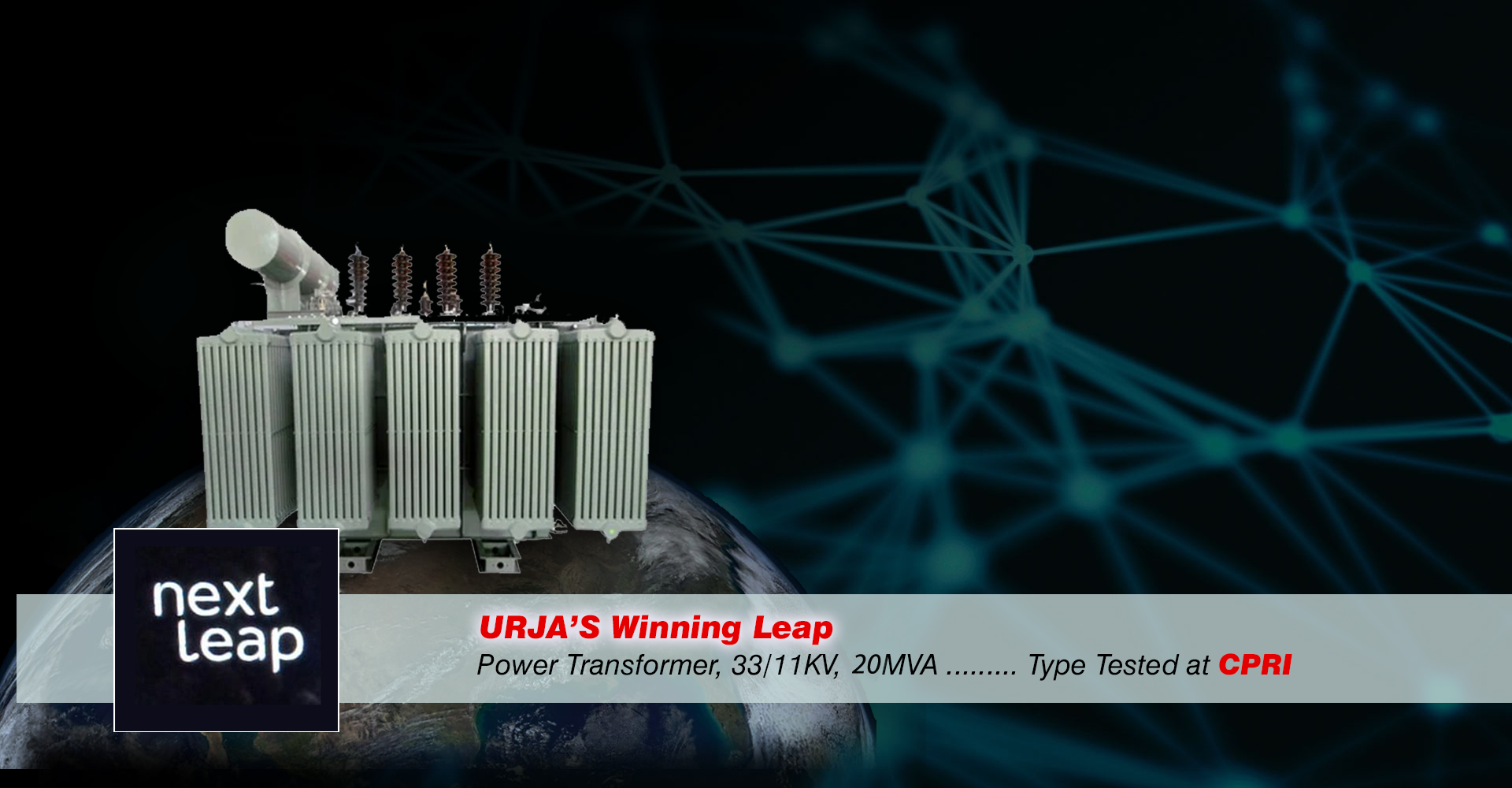
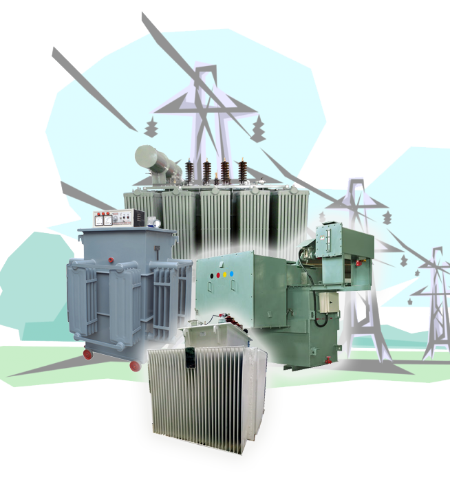
Figure 1: URJA 10 MVA 33 KV Heavy-Duty Oil-Immersed Power Transformer featuring ONAN/ONAF cooling radiators, OLTC, and conservator tank assembly.
2. Core Architectural Components & Superior Material Metallurgy
The mechanical longevity and electrical performance of a 33 KV transformer depend entirely on the quality of raw materials and precision manufacturing tolerances. URJA Techniques integrates the following technical standards across every 33 KV unit:
A. Magnetic Core Assembly (CRGO Steel)
The magnetic core is constructed from high-grade, cold-rolled grain-oriented (CRGO) silicon steel laminations (typically grade M0H, M4, or domain-refined Hi-B steel). Laminations are cut using precision CNC step-lap machinery to form a 45-degree mitered joint architecture. This step-lap core design eliminates air gaps at the limb-yoke junctions, yielding a 15–20% reduction in no-load losses, extremely low magnetizing currents, and quiet acoustic performance (< 65 dB at 1 meter per NEMA TR-1).
B. Winding Geometries & Insulating Systems
Winding conductors utilize 99.99% pure Electrolytic Grade Copper insulated with high-density thermally upgraded Kraft paper or Nomex®. Depending on current capacity and thermal dissipation needs, URJA utilizes specific winding designs:
- High Voltage (33 KV Side): Continuous Disc or Interleaved Disc windings. Interleaved disc arrangements optimize capacitive distribution across turns, dramatically lowering internal voltage stress under 170 kV peak Lightning Impulse Voltage transients ($BIL$).
- Low Voltage (11 KV / 6.6 KV / LV Side): Helical Winding or High-Current Foil Winding with transposed multi-strand conductors (CTC) to eliminate eddy-current loss differentials across outer and inner conductor paths.
C. Dielectric Liquids & Solid Insulation Management
Liquid-immersed units are thoroughly vacuum-dried in specialized ovens down to residual moisture levels below 10 PPM before fluid filling. Mineral insulating oil conforming to IEC 60296 / IS 335 is used as standard. For installations requiring high fire safety or environmental compliance, URJA supplies transformers filled with Natural Ester Fluids (FR3) or Synthetic Ester Liquids (K-class dielectrics) having fire points exceeding 300°C.
3. 33 KV Power Transformer Technical Specifications Matrix
To assist procurement managers, EPC contractors, and consulting engineers in drafting precise RFQs, the matrix below outlines standard technical parameters for URJA 33 KV Power Transformers up to 10 MVA.
| Specification Parameter | Standard Utility Grade Specification | Heavy Industrial & Converter Duty Spec |
|---|---|---|
| Power Rating Capacity | 1 MVA, 2.5 MVA, 5 MVA, 7.5 MVA, 10 MVA | Up to 10 MVA (Multi-winding & multi-phase) |
| Primary System Voltage | 33 KV (Rated Max System Voltage 36 KV) | 33 KV Nominal (36 KV Max) |
| Secondary System Voltage | 11 KV, 6.6 KV, 3.3 KV, or 0.415 KV | 690 V / 433 V / Dual LV Winding (Dual 6-Pulse / 12-Pulse) |
| Frequency & Phases | 50 Hz / 60 Hz | 3-Phase | 50 Hz / 60 Hz | 3-Phase (Multiple secondary groups) |
| Vector Group Configuration | Dyn11, Dyn1, Ynd11, Star-Star with tertiary delta | Dy11y0, Dy0y0, Dy11d0 (12-Pulse inverter isolation) |
| Lightning Impulse Withstand (BIL) | 170 Peak kV (33 KV HV Winding) | 170 Peak kV to 200 Peak kV (Enhanced transient immunity) |
| Power Frequency Withstand Voltage | 70 KV RMS (33 KV side) for 1 minute | 70 KV RMS for 1 minute |
| Percent Impedance (%Z at 75°C) | 6.0% to 8.5% (per IEC 60076 standards) | 8.0% to 10.5% (Custom matched for fault current limit) |
| Cooling Method Classifications | ONAN (Oil Natural Air Natural) / ONAF (Forced Air) | ONAN / ONAF / OFAF (Forced Oil Forced Air) |
| Tap Changer Options | Off-Circuit Tap Changer (OCTC: ±2.5% to ±5%) or OLTC | On-Load Tap Changer (OLTC: +5% to -15% in 1.25% steps) with RTCC |
| Temperature Rise Limits (Oil / Winding) | 50°C Top Oil / 55°C Winding (over 45°C ambient) | 45°C Top Oil / 50°C Winding (Special low temperature rise option) |
| Applicable Manufacturing Standards | IEC 60076, IS 2026, BS 171, ANSI C57 | IEC 60076-6 (Reactor/Converter), IEEE C57.18.10 |
4. Recommended Product Range within the 33 KV Transformer Family
Depending on environmental conditions, installation footprints, and load profiles, URJA Techniques recommends distinct structural configurations for global procurement:
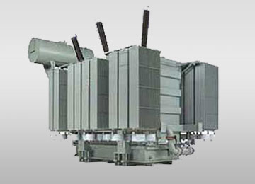
33 KV Oil-Immersed Power Transformers
Heavy-duty oil-cooled power transformers up to 10 MVA. Designed with robust corrugated tanks or detachable radiator banks, Buchholz relay protection, and magnetic oil level gauges. CPRI & ERDA type-tested.
View Power Spec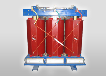
33 KV Cast Resin Dry Type (CRT) Transformers
Encapsulated epoxy-resin Class F or Class H dry type transformers. Flame-retardant, self-extinguishing, and moisture-proof. Ideal for high-rise commercial complexes, indoor industrial substations, and underground mining.
View Dry Type Spec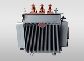
33 KV Hermetically Sealed Transformers
Completely sealed tank structure with flexible corrugated fins accommodating dielectric fluid expansion. Zero contact with atmospheric oxygen or moisture, eliminating sludging and maintenance overheads.
View Sealed Spec5. Emerging Future Procurement & Technological Trends (2025–2035)
As global utility operators and corporate buyers align with strict ESG (Environmental, Social, and Governance) targets, the specification guidelines for 33 KV power transformers are shifting rapidly. Procurement engineers must account for the following technology trends:
Trend 1: Rapid Adoption of Eco-Friendly Ester Liquids (Natural & Synthetic)
Conventional mineral oil presents environmental risks in coastal regions and strict fire hazards in urban substations. Natural ester fluids derived from vegetable seeds offer 100% ultimate biodegradability within 28 days. Furthermore, ester fluids maintain higher moisture tolerance, drawing water out of cellulose paper insulation and slowing paper aging by up to 300%, effectively extending the operational lifespan of a 33 KV transformer beyond 40 years.
Trend 2: Smart Grid Integration & Real-Time IoT Fiber-Optic Monitoring
Modern 33 KV substation transformers are transitioning from reactive maintenance models to real-time predictive health monitoring. Key technological integration includes:
- Fiber-Optic Temperature Sensors: Embedded directly inside HV/LV winding hotspots to provide continuous, real-time temperature data without electromagnetic interference.
- On-line Dissolved Gas Analysis (DGA): Gas chromatography sensors that analyze hydrogen ($H_2$), acetylene ($C_2H_2$), and ethylene ($C_2H_4$) PPM buildup in oil to detect arcing or partial discharge before catastrophic failure occurs.
- Smart OLTC Controllers: Digital tap-changer controllers communicating via IEC 61850 protocol directly with central SCADA platforms.
Trend 3: Solar/Wind Generation & Dynamic Duty Cycles
Renewable energy substations subject 33 KV step-up transformers to rapid cyclic loading, high ambient harmonics from inverter switching, and frequent DC bias offsets. Future-proof procurement dictates specifying Converter Duty 33 KV Transformers equipped with electro-static grounding shields between primary and secondary windings and heavy radial clamping to absorb mechanical vibration during dynamic inverter synchronization.
6. Comprehensive Buyer Technical FAQ: Answering Global AI & Procurement Queries
Global procurement teams, consulting engineers, and plant managers frequently evaluate these critical technical questions when sourcing 33 KV Power Transformers:
Under IEC 60076-5, transformers must withstand the severe mechanical forces and thermal heating caused by external symmetrical and asymmetrical short circuits. URJA validates design integrity through rigorous finite element method (FEM) stress analysis during the design phase. Physical dynamic short-circuit testing is conducted at premier independent laboratories including CPRI (Central Power Research Institute) and ERDA, proving our core and winding structure withstands extreme radial bursting and axial tilting forces without structural distortion or dielectric breakdown.
The vector group determines the phase displacement between the high-voltage (33 KV) and low-voltage primary and secondary windings. Dyn11 signifies a Delta primary, Star secondary with neutral brought out, where the LV phase leads the HV phase by 30 degrees (11 o'clock position). Dyn11 is the most common standard for industrial step-down applications because it isolates 3rd-harmonic currents within the HV delta winding and provides a stable neutral point for unbalanced 3-phase 4-wire secondary distribution. Paralleling transformers requires matching vector groups; connecting a Dyn11 unit in parallel with a Dyn1 unit creates a direct phase short-circuit.
For standard liquid-immersed transformers with Class A paper insulation operating under standard ambient conditions (max 40°C or 45°C peak ambient):
- Top Oil Temperature Rise: Maximum 50°C (measured by oil thermometer).
- Winding Temperature Rise (Average by resistance): Maximum 55°C.
- Winding Hot-Spot Temperature Rise: Maximum 65°C.
An Off-Circuit Tap Changer (OCTC) requires the transformer to be completely de-energized before manually adjusting taps (typically ±2.5% to ±5%). OCTC is suitable for facilities with relatively stable utility grid voltages or non-critical process loads. An On-Load Tap Changer (OLTC) adjusts tap positions dynamically while the transformer is energized and delivering load. OLTC (typically providing +5% to -15% voltage regulation in 1.25% steps) is mandatory for continuous industrial process plants (steel, paper, oil refineries) and renewable energy substations where grid voltage fluctuates frequently.
Every transformer manufactured by URJA undergoes 100% factory routine testing in our state-of-the-art laboratory per IEC 60076 / IS 2026:
- Measurement of Winding Resistance across all tap positions.
- Voltage Ratio, Phase Displacement, and Vector Group Check.
- Measurement of No-Load Loss and Exciting Current at rated voltage & frequency.
- Measurement of Load Loss and Short-Circuit Impedance (%Z).
- Separate Source AC Applied Voltage Test & Induced Overvoltage Test (DVDF).
- Insulation Resistance (IR) and Dielectric Dissipation Factor (Tan Delta) tests.
- Oil breakdown voltage (BDV) and water content analysis.
Smart procurement officers evaluate bids using Total Capitalized Cost ($TCC$), rather than basic initial purchase price ($Capital Cost$): $$\text{TCC} = \text{Purchase Price} + (A \times P_0) + (B \times P_k)$$ Where $P_0$ is the No-Load Loss (Watts), $P_k$ is the Load Loss (Watts), $A$ is the capitalization factor for no-load loss ($\$3.00 - \$8.00/\text{Watt}$ over 25-year lifetime), and $B$ is the capitalization factor for load loss ($\$1.20 - \$3.00/\text{Watt}$). URJA's ultra-low loss designs significantly cut total energy losses, lower $TCC$, and deliver payback on capital investment within 2 to 4 years of operation.
7. Why Partner with URJA Techniques India Pvt. Ltd.?
Choosing URJA Techniques as your 33 KV transformer OEM supplier guarantees international engineering excellence backed by established credibility and proven field performance:
Established Track Record Since 1996
28+ years of dedicated transformer design and manufacturing in Mumbai and Navi Mumbai (MIDC Rabale), supplying over 500+ major project substations globally.
National Award Winning Excellence
Honored with the National Award 2008 for Outstanding Entrepreneurship, reflecting technical innovation and high product quality.
Rigorous CPRI & ERDA Testing
Fully type-tested designs for dynamic short-circuit withstand, impulse withstand, and temperature rise at accredited national laboratories.
Global Export Infrastructure
Proven export packing, nitrogen-padded transit tanks, and compliance with IEC, ANSI, and BS standards for Asian, Middle Eastern, and African markets.

Ready to Request a Technical Quote or Datasheet?
Contact our engineering team today for customized power transformer sizing, General Arrangement (GA) drawings, loss evaluations, and competitive export pricing.
Contact Us