
EN
0%

Choosing the right Reactor Transformer is not a nameplate exercise. It is a system decision. Load profile, harmonic distortion, voltage variation, cooling method, insulation level, and available installation space must be reviewed together. A unit that looks suitable on paper may overheat beside a variable-frequency drive, hum loudly near sensitive equipment, or suffer premature insulation aging.

John J. Winders Jr., author of Power Transformers: Principles and Applications, offers a practical engineering reminder: “Transformer selection must begin with the system’s actual duty, not its catalog description.” That principle remains useful, although real projects are rarely so tidy. Site measurements may be incomplete. Future expansion may be unclear. Engineers sometimes accept optimistic load data. That mistake can become expensive.

A reliable Reactor Transformer should match the reactor’s inductive behavior, operating voltage, current, frequency, and expected transients. Check impedance carefully. Confirm short-circuit strength. Review thermal performance under continuous and intermittent loads. Also inspect enclosure protection, noise limits, tap arrangements, and maintenance access. Small details matter. A cramped terminal box complicates testing. Poor ventilation raises winding temperature. Inadequate harmonic evaluation can distort the expected loss calculation.

The best choice balances technical performance, lifecycle cost, safety, and serviceability. It should also leave a sensible margin, not an arbitrary oversize allowance. No selection method is perfect. Good engineering records its assumptions, challenges them, and updates them when field evidence disagrees.
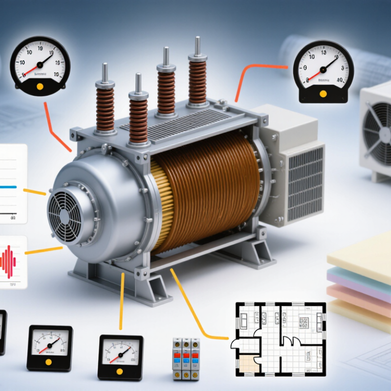
How to Choose the Right Reactor Transformer?

Define Reactor Transformer Ratings: Voltage, MVA, Frequency, and Duty Cycle

How to Choose the Right Reactor Transformer?

A reactor transformer must be rated from actual operating conditions, not only the nameplate load. Start with primary and secondary voltage, including tap range and insulation level. IEC 60076-1 requires transformer ratings to reflect specified voltage, frequency, and service conditions. A small voltage mistake can increase core flux, heating, and audible noise.

MVA is not simply kilowatts divided by power factor. Rectifier loads, motor drives, and furnaces can create harmonics and reactive current. Calculate the fundamental load, harmonic heating, and required overload margin together. IEEE C57.12.00 provides a useful basis for transformer ratings and temperature limits. Field measurements matter. According to the IEA Electricity 2024 report, global electricity demand is expected to grow by about 4% annually through 2026, increasing pressure on dependable conversion equipment.

Frequency also deserves attention. A 50 Hz transformer should not be treated as a 60 Hz unit without checking flux density and thermal performance. Define the duty cycle clearly: continuous, short-time, cyclic, or emergency. Record load duration, starts per hour, ambient temperature, and cooling method. IEC 60076-7 explains how loading affects insulation ageing and permissible temperatures. A forgotten 30-minute overload can change the design.

Some specifications remain imperfect. Load data may be estimated. Harmonic measurements may be missing. That uncertainty should be stated, not hidden. Require tested losses, impedance, temperature-rise data, and factory acceptance records before approval.

Match Impedance and Short-Circuit Withstand to IEEE C57.12.00 Criteria

How to Choose the Right Reactor Transformer?

Impedance is not a decorative nameplate value. It controls voltage regulation and available fault current. For a transformer feeding a reactor, calculate both operating and fault conditions. A 10% impedance theoretically limits symmetrical fault current to about ten times rated current. Lower impedance improves voltage performance, but it can increase mechanical stress during a fault.

IEEE C57.12.00-2021 provides general requirements and impedance tolerances for liquid-immersed transformers. IEEE C57.12.90-2021 describes short-circuit and other test methods. Confirm the specified impedance, tolerance, X/R ratio, and fault duration together.

A small tolerance shift can affect relay coordination. It can also change the reactor’s expected current waveform. Check the details.

The short-circuit design must withstand thermal I²t energy and the first asymmetrical current peak. Do not compare only the RMS fault value. System grounding, bus strength, and transformer connection influence the actual stress.

The U.S. Department of Energy’s Large Power Transformers and the U.S. Electric Grid report identifies transformer lead times exceeding 20 months in constrained periods. That makes factory verification important before procurement. The Energy Information Administration’s Electric Power Annual reports U.S. transmission and distribution losses near 5% of generation, reminding engineers that operating efficiency still matters. A technically strong design can fail commercially when its impedance assumptions are incomplete. Require documented calculations, routine tests, and short-circuit design evidence before approving the transformer-reactor package.

Select Insulation Levels Using IEC 60076 and System BIL Requirements

How to Choose the Right Reactor Transformer?

Insulation coordination starts with the system, not the transformer nameplate. IEC 60076-3 defines dielectric tests, including power-frequency, induced-voltage, lightning-impulse, and switching-impulse withstand levels. IEC terminology uses LI and SI ratings, while BIL commonly describes lightning-impulse withstand in North American practice. These terms should be aligned before procurement documents are issued.

Measure the system’s highest operating voltage, grounding method, switching duties, and arrester protective level. Then compare the transformer’s LI and SI withstand values with the network’s required BIL. The selected insulation level needs a practical margin above the arrester’s residual voltage. At the bushing, a 1.2/50 μs impulse can expose weak clearances that normal factory tests will not reveal. Reactor switching deserves special attention. Its steep transients may stress turn insulation and terminal connections repeatedly.

CIGRE Technical Brochure 642, Transformer Reliability Survey, reviewed 964 failure events and identified winding insulation and connected components as recurring contributors. That evidence supports detailed impulse coordination, not simply choosing the highest available rating. Field engineers should also check altitude correction, oil gaps, creepage distance, and transport conditions.

A reactor transformer may pass routine tests yet remain vulnerable to repetitive switching surges. This is where a design review can become uncomfortable. Calculated margins may look sufficient, but incomplete system data can make them optimistic. Record the actual arrester voltage, cable length, and switching sequence before finalizing IEC 60076 insulation levels.

Compare Cooling Classes: ONAN, ONAF, and Load-Driven Temperature Rise

How to Choose the Right Reactor Transformer?

Cooling class directly affects reactor transformer capacity, noise, maintenance, and service life. ONAN uses natural oil circulation and natural air cooling. It is simple, quiet, and suitable for steady loads. ONAF adds fans when the winding temperature rises. This can increase usable capacity without greatly enlarging the tank. However, fans add controls, vibration, and failure points.

IEC 60076-2 defines temperature-rise methods for power transformers, while IEEE C57.12.00 provides widely used requirements for liquid-immersed units. The U.S. Department of Energy reported that transformer losses consume about 61 billion kWh annually in its technical support analysis. That figure covers distribution transformers, not reactor units. Still, it shows why cooling selection deserves serious attention. In the field, a reactor with frequent harmonic loading may run hotter than its average current suggests. A neat load calculation can mislead. Heat follows the real waveform, not the spreadsheet alone.

Tips: Record daily current, ambient temperature, harmonics, and fan operation. Choose ONAN when load is stable and access is limited. Consider ONAF when short-term overloads are common. For load-driven temperature rise, set alarms conservatively and test fan staging under heat. Do not rely on nameplate ratings alone. Check oil flow, radiator cleanliness, and winding hot-spot calculations. A lower initial cost may become expensive after repeated thermal cycling.

How to Choose the Right Reactor Transformer? - Compare Cooling Classes: ONAN, ONAF, and Load-Driven Temperature Rise

Evaluation Dimension ONAN ONAF Load-Driven Temperature Rise Selection Implication
Cooling designation Oil Natural, Air Natural. Transformer oil circulates by buoyancy and heat is released to surrounding air through radiators or corrugated tank surfaces. Oil Natural, Air Forced. Oil circulation remains natural, while fans force air across the radiators or coolers. Not a separate IEC cooling-code designation. It describes how winding temperature rise increases with load and decreases when load falls. Use the formal cooling code on the nameplate, and evaluate temperature rise separately for the expected load profile.
Heat-transfer mechanism Natural oil circulation transfers heat from the windings and core to the tank and radiators; natural air movement removes heat from the radiator surfaces. Natural oil circulation transfers heat to the radiators, and fan-generated airflow increases the rate of heat rejection to ambient air. Copper and stray-load losses generally increase approximately with the square of current, so thermal stress rises sharply during high-load periods. Confirm that the cooling arrangement can remove heat at the maximum continuous load and during specified overload conditions.
Typical operating use Suitable where the required rating can be achieved without fans, including many distribution, auxiliary, and moderate-capacity power transformer applications. Suitable where a higher continuous rating or greater short-term loading capability is needed without using forced-oil circulation. Most relevant to variable-load substations, renewable-energy interfaces, industrial facilities, and installations with daily or seasonal demand changes. Match the cooling mode to the actual duty cycle rather than selecting solely by nominal nameplate rating.
Fan requirement No cooling fans are required for the stated ONAN rating. Cooling fans, fan motors, controls, alarms, and suitable auxiliary power are required for the ONAF rating. Fans may be staged or controlled by winding-oil temperature, load current, calculated hot-spot temperature, or a combination of these inputs. Check fan redundancy, automatic start logic, manual override, alarm contacts, and operation after loss of auxiliary power.
Response to increasing load Temperature rises as losses increase. Heat removal is limited by natural convection and radiator surface area. Fans increase heat rejection when activated, allowing the transformer to maintain a lower temperature rise than ONAN at comparable loading. Temperature does not change instantaneously because the oil, windings, and tank have thermal inertia; sustained high load produces a progressively higher hot-spot temperature. Use thermal models and time-current loading data when evaluating cyclic loading or emergency overloads.
Efficiency and auxiliary consumption No fan power is consumed. This simplifies operation and avoids fan-related auxiliary losses. Fan motors consume auxiliary power when operating; the consumption depends on fan size, quantity, control sequence, and operating hours. Load-dependent fan staging can reduce unnecessary auxiliary consumption during low-load periods. Compare total ownership cost, including auxiliary energy, maintenance, and the value of increased available capacity.
Reliability considerations Fewer active cooling components generally mean fewer fan, motor, control, and auxiliary-power failure points. Reliability depends on fan availability, control-panel condition, auxiliary supply, ventilation, and the ability to continue operation if one fan fails. Repeated high-temperature operation accelerates insulation ageing; monitoring and appropriate loading limits are essential. For critical service, define an acceptable reduced-rating condition for fan failure and specify alarms before thermal limits are reached.
Noise and site impact Usually produces lower operating noise because there are no cooling fans. Fan noise and airflow may increase the overall sound level, especially when multiple fans operate simultaneously. Noise varies with the loading schedule and fan-control thresholds. Consider acoustic limits, nearby buildings, airflow clearance, dust exposure, and access for fan maintenance.
Maintenance profile Routine work focuses on oil condition, bushings, connections, radiators, tank integrity, and temperature-monitoring devices. Includes ONAN maintenance plus inspection, cleaning, testing, lubrication where applicable, and replacement planning for fans and controls. Temperature records, alarm history, load cycles, and hot-spot estimates should be reviewed to identify excessive thermal ageing. Choose ONAF when the additional capacity justifies the added maintenance and auxiliary-system requirements.
Key design data to request Rated power, voltage ratio, impedance, ambient design conditions, temperature-rise limits, radiator arrangement, and applicable insulation system. All ONAN data plus fan-assisted rating, number of fan stages, auxiliary voltage, fan airflow, control thresholds, and reduced-capacity operation after fan failure. Load duration curve, maximum and average load, ambient-temperature profile, permissible overload duration, hot-spot limits, and monitoring accuracy. A complete load profile is more useful than a single peak-load value when comparing cooling options.
Engineering note: Actual permissible temperature rise, continuous ratings, overload capability, and alarm or trip settings depend on the applicable standard, insulation system, transformer design, ambient conditions, and manufacturer’s guaranteed data. Cooling classes are commonly identified using IEC 60076-2 nomenclature; verify the project requirements against the governing specification.

Verify Harmonic, Noise, Efficiency, and Compliance Requirements Before Purchase

How to Choose the Right Reactor Transformer?

A reactor transformer should be selected from measured site conditions, not only the equipment rating. Harmonic current can heat windings, increase losses, and disturb sensitive controls. Request a harmonic study covering the fundamental frequency, expected load profile, and total harmonic distortion. A unit that performs well at full load may behave differently during light-load operation.

Noise also deserves a practical check. A transformer installed beside offices, laboratories, or production lines may need strict sound limits. Ask for guaranteed sound pressure data and clarify the measurement distance. Efficiency should be verified across realistic loading conditions, not only at the nameplate rating. I have seen projects focus on peak efficiency while ignoring long periods at partial load. That choice can raise operating costs quietly.

Tips: Confirm ambient temperature, altitude, enclosure ventilation, and duty cycle before approval. Check whether the design handles inrush current and repeated switching. Review insulation levels, temperature rise, testing procedures, and applicable electrical standards with a qualified engineer. Keep the compliance documents with the purchase record. They matter later. Finally, compare measured harmonic and acoustic data with the site limits. Some specifications look complete but leave testing methods unclear. That gap needs attention before procurement.

FAQS

What information is needed to rate a reactor transformer correctly?

Provide primary and secondary voltage, tap range, frequency, insulation level, ambient temperature, and cooling method.

How should the transformer MVA rating be calculated?

Include fundamental load, reactive current, harmonic heating, and the required overload margin.

Does frequency affect reactor transformer selection?

Yes. A 50 Hz design should not automatically operate at 60 Hz.

How should the duty cycle be specified?

State whether operation is continuous, short-time, cyclic, or emergency.

What harmonic information should be requested before purchase?

Request measured harmonic current, total harmonic distortion, load profile, and expected light-load behavior.

How are insulation levels selected?

Start with the system’s highest voltage, grounding method, switching duties, and arrester protective level.

Why do reactor switching events require special attention?

Repeated switching can create steep transients at terminals and windings.

What noise and efficiency details should be verified?

Request guaranteed sound pressure data and state the measurement distance.

Which tests and records should be required before approval?

Require tested losses, impedance, temperature-rise results, insulation tests, and factory acceptance records.

Conclusion

Choosing the right Reactor Transformer begins with defining the application clearly. Confirm the required voltage, MVA capacity, operating frequency, and duty cycle, including expected overloads and switching conditions. The transformer’s impedance should be coordinated with the system’s short-circuit level and withstand requirements in accordance with IEEE C57.12.00 criteria. Insulation selection is equally important: evaluate system voltage, Basic Insulation Level (BIL), transient exposure, and applicable IEC 60076 requirements to ensure dependable operation and suitable protection margins.

Cooling performance must match the expected load profile and installation environment. ONAN systems may suit steady, moderate loading, while ONAF or load-driven cooling can provide additional capacity during changing demand. Before purchase, review harmonic heating, acoustic noise, efficiency, temperature rise, maintenance needs, and documentation. Confirm that the proposed design satisfies all applicable technical and compliance requirements, and verify test data, installation conditions, and future expansion plans. A complete evaluation helps ensure reliable performance, controlled operating costs, and long-term system compatibility.

Sophie

Sophie

Sophie is a dedicated marketing professional with a deep expertise in our company’s products and services. With a passion for showcasing the unique advantages of our offerings, she plays a crucial role in crafting insightful content for our professional blog. Through her well-researched articles,......