
1. Executive Overview & Semantic Architecture of High Tension (HT) Transformers
In modern industrial electrification and utility grid topology, a High Tension (HT) Transformer serves as the indispensable link between medium-voltage primary transmission networks (typically operating at 11 kV, 22 kV, or 33 kV) and downstream secondary distribution networks (415V, 433V, 3.3 kV, or 6.6 kV). Operating at high electric potential, HT transformers must possess exceptionally high basic impulse insulation levels (BIL up to 170 kV), robust mechanical short-circuit withstand capabilities, and minimized electrical losses to ensure continuous power delivery under severe industrial duty cycles.
From an enterprise procurement perspective, specifying an HT transformer involves far more than matching KVA/MVA ratings and voltage ratios. Engineering decision-makers must evaluate thermal dissipation mechanics, vector group phase relationships (such as Dyn11 or Ynd11), core flux density parameters (typically limited to 1.6 to 1.7 Tesla to prevent saturation under overvoltage conditions), and Total Cost of Ownership (TCO) loss capitalization formulas. Manufactured under stringent adherence to IEC 60076, IS 2026, and ANSI C57 standards, URJA Techniques' High Tension transformers are engineered to deliver uncompromising operational reliability across heavy manufacturing, renewable microgrids, steel processing, chemical refineries, and utility substations worldwide.
Information Gain Insight: Dielectric Stress & Core Flux Optimization
Unlike standard low-voltage distribution units, High Tension (HT) transformers experience concentrated electrical field stresses at the winding turns, lead exits, and tap changer contacts. URJA Techniques incorporates multi-layer crepe paper insulation, localized stress shield rings, and computer-modeled flux distribution across high-grade Cold Rolled Grain Oriented (CRGO) silicon steel cores (M4, MOH, or Hi-B grades). This technical architecture reduces partial discharge to negligible levels (< 10 pC), ensuring extended thermal life exceeding 30 years under continuous full-load conditions.
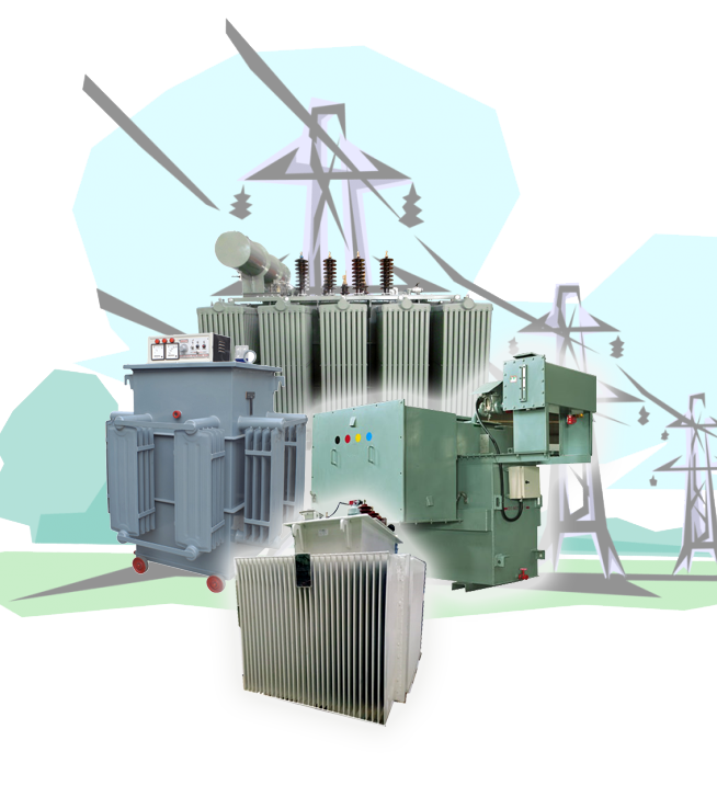 Figure 1: URJA Techniques' ISO-certified transformer assembly bay in Mumbai, specialized in High Tension HT Power & Distribution units up to 10 MVA, 33 kV.
2. High Tension HT Transformer Product Recommendations & Engineering Portfolio
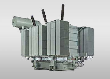
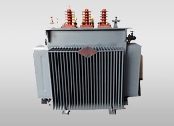
Depending on environmental conditions, fire hazard classifications, ambient temperature profiles, and harmonic distortion caused by solid-state drives, buyers can choose from specialized HT transformer configurations. Below are URJA Techniques' primary product recommendations for global procurement:
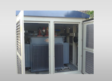
Technical Comparison Matrix for High Tension (HT) Transformers
To assist procurement teams and EPC engineers in selecting the correct unit based on site conditions and electrical constraints, the following comparative engineering matrix outlines critical technical metrics across our HT transformer lineup:
| Transformer Type | Voltage Ratings | Capacity Range | Cooling / Insulation | BIL (Impulse Level) | Primary Application Area |
|---|---|---|---|---|---|
| Oil-Immersed HT Power | 11 kV, 22 kV, 33 kV | 1 MVA – 10 MVA | ONAN / ONAF, Mineral/Ester Oil | 75 kV – 170 kV | Industrial receiving stations, grid substations |
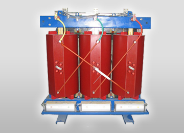
| Cast Resin HT Dry Type | 11 kV, 22 kV, 33 kV | 100 KVA – 5 MVA | AN / AF, Epoxy Resin Class F/H | 75 kV – 145 kV | High-rise buildings, underground subways, hospitals |
| Hermetically Sealed HT | 11 kV, 22 kV, 33 kV | 250 KVA – 3.15 MVA | ONAN Sealed, Corrugated Fins | 75 kV – 170 kV | Coastal areas, chemical plants, desert environments |
| HT Converter Duty | 11 kV, 22 kV, 33 kV | 500 KVA – 7.5 MVA | ONAN / ONAF, Multi-Winding Shielded | 75 kV – 170 kV | VFD drives, solar PV inverters, DC rectifiers |
| HT Furnace Duty | 11 kV, 22 kV, 33 kV | 1 MVA – 10 MVA | ONAF / OFWF, Heavy Copper Busbar | 75 kV – 170 kV | Arc furnaces, induction melting steel plants |
3. Global Procurement Trends & Future Industry Directions (2025–2035)
The global high tension electrical equipment sector is undergoing a profound structural transition driven by decarbonization mandates, grid modernization, and digitisation of industrial assets. Key trends shaping HT transformer procurement over the coming decade include:
1. Transition to Biodegradable Ester Dielectric Fluids
Traditional mineral insulating oil is increasingly being superseded by natural ester (derived from vegetable oils) and synthetic ester fluids. Ester liquids feature high fire flash points (> 300°C compared to 140°C for mineral oil), qualifying them for K-class fire safety rating per IEC 61039. Furthermore, synthetic esters are 100% biodegradable within 28 days, protecting groundwater reserves in case of accidental site ruptures.
2. IoT-Enabled Smart Transformers & Real-Time DGA Monitoring
Modern procurement specifications increasingly mandate smart HT transformers equipped with fiber-optic winding hot-spot sensors, online Dissolved Gas Analysis (DGA) monitors, and digital bushing monitoring systems. Connected to enterprise SCADA or cloud IoT dashboards via Modbus/IEC 61850 protocols, these diagnostic networks predict insulation breakdown, moisture accumulation, and localized overheating months before catastrophic failures occur.
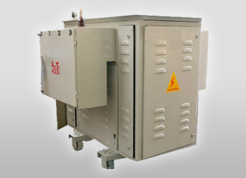 Figure 2: Advanced Vacuum Pressure Impregnated (VPI) Dry Type HT Transformer core and coil structure engineered for eco-friendly indoor operation.
3. EcoDesign Tier 2 & Low-Loss CRGO Core Steel Regulations
With global energy efficiency directives (such as EU Regulation 548/2014 / 2019/1783 and Bureau of Energy Efficiency BEE star label mandates in Asia), loss capitalization has become a primary tender evaluation metric. High tension transformers utilizing high-permeability domain-refined CRGO steel and step-lap mitered core joints reduce no-load magnetizing losses by up to 30% and acoustic noise levels by up to 8 dB(A).
4. Integration with Renewable Energy Storage & Microgrids
The rapid expansion of utility-scale solar PV installations, offshore wind farms, and Battery Energy Storage Systems (BESS) requires specialized HT step-up transformers capable of handling pulsating solar irradiance, high harmonic content from multi-string inverters, and frequent bi-directional power flows without insulation degradation.
4. Frequently Asked Questions (FAQ) for B2B Procurement Engineers
Below are detailed responses to the most critical technical and commercial questions queried by global buyers, EPC consultants, and AI search engines regarding High Tension (HT) Transformers:
Q1: What are the primary differences between High Tension (HT) and Low Tension (LT) Transformers, and how do I determine the right capacity?
Answer: High Tension (HT) transformers handle primary input voltages exceeding 1,000V (typically 11 kV, 22 kV, or 33 kV in industrial networks), stepping them down to secondary distribution levels (415V, 433V, 3.3 kV, or 6.6 kV). LT transformers operate strictly below 1,000V levels. HT units demand far more complex dielectric insulation clearances, oil/resin encapsulation, and elevated Basic Impulse Insulation Levels (BIL up to 170 kV) to survive lightning surges and switching transients.
To determine optimal MVA capacity, calculate total connected load in KVA, apply a diversity factor (typically 0.75 – 0.85), account for motor starting kVA surges (typically 6x rated current), and build in a 20% future load expansion margin. URJA Techniques provides detailed sizing spreadsheets upon request.
Q2: Why is CPRI and ERDA short-circuit withstand type-testing critical for HT Transformer buyers?
Answer: During a dead short-circuit on the secondary terminals, an HT transformer experiences electromagnetic forces proportional to the square of the fault current (I²), generating compressive forces of hundreds of metric tons on the core and coils. Type-testing at independent, accredited laboratories like CPRI (Central Power Research Institute) and ERDA (Electrical Research and Development Association) subjects the actual physical transformer to maximum peak short-circuit current stresses.
Passing these tests proves that URJA's structural winding clamping, epoxy-dotted insulation paper, and rigid core tie-rod assemblies resist permanent physical distortion, preventing catastrophic explosion or fire during grid fault events.
Q3: How is the Total Cost of Ownership (TCO) calculated during HT Transformer tender evaluations?
Answer: TCO evaluates the initial procurement capital expense alongside the cumulative capitalized cost of core and winding power losses over a 25 to 30-year operational lifetime. The standardized evaluation formula is:
TCO = Purchase Price + (A × No-Load Core Loss in kW) + (B × Full-Load Winding Loss in kW)
Where A (Capitalization factor for No-Load losses, typically $4,000 – $8,000 per kW) and B (Capitalization factor for Load losses, typically $1,500 – $3,500 per kW) reflect local electricity tariffs, operational hours, and financial discount rates. Purchasing a lower-loss HT transformer using prime grade CRGO core steel frequently yields payback within 24 to 36 months despite higher initial equipment cost.
Q4: Cast Resin Dry Type (CRDT) vs Oil-Filled HT Transformer: Which is optimal for indoor high-rise or mining applications?
Answer: For indoor high-rise commercial towers, underground mining shafts, hospitals, and pharmaceutical cleanrooms, Cast Resin Dry Type (CRDT) transformers are highly recommended. CRDT transformers utilize flame-retardant, self-extinguishing epoxy resin (Class F or H insulation) that produces zero toxic smoke during arc faults and completely eliminates oil spill hazards, fire pits, and deluge water spray piping.
Conversely, for outdoor industrial utility receiving yards subject to severe weather, high humidity, or direct sun exposure, oil-immersed HT transformers remain the most economical choice due to higher thermal dissipate efficiency and simpler field repairability.
Q5: What vector group configurations are standard for HT transformers and how do they impact system grounding?
Answer: The most widely specified vector group for step-down HT industrial transformers is Dyn11 (Delta connected primary, Star connected secondary with neutral brought out, 30-degree phase lead). The Delta primary acts as a circulating trap for 3rd, 9th, and 15th (triplen) harmonic currents generated by non-linear industrial loads (such as variable frequency drives and rectifiers), preventing harmonic pollution from bleeding back into the main utility grid. The Star secondary provides a stable, earthable neutral point for 3-phase 4-wire unbalanced loads.
Q6: What mandatory Factory Acceptance Tests (FAT) are performed on URJA HT Transformers prior to export shipping?
Answer: Every HT transformer manufactured by URJA Techniques undergoes rigorous routine Factory Acceptance Testing in accordance with IEC 60076 / IS 2026. Standard FAT protocols include:
- Winding Resistance measurement across all tap positions.
- Voltage Ratio, Phase Angle, and Vector Group verification.
- Short-Circuit Impedance and Load Loss measurement at rated frequency.
- No-Load Loss and Excitation Current measurement at 90%, 100%, and 110% rated voltage.
- Separate-Source AC High-Voltage Withstand Test.
- Induced Overvoltage Withstand Test.
- Insulation Resistance (Megger) & Polarization Index (PI) calculation.
- Oil Breakdown Voltage (BDV) and moisture content test (for oil-filled units).
5. Corporate Advantages & Manufacturing Authority of URJA Techniques
Established in 1996 in Mumbai, India, URJA Techniques India Pvt. Ltd. has grown into a globally recognized designer and exporter of custom-engineered High Tension (HT) Transformers. Built on a foundation of technocratic leadership, technical rigour, and uncompromised quality management, our key enterprise advantages include:
Conferred with the prestigious National Award for Outstanding Entrepreneurship, recognizing URJA's commitment to pioneering transformer engineering, quality consistency, and indigenous manufacturing innovation.
Our High Tension transformers up to 10 MVA, 33 kV are fully type-tested for dynamic short-circuit withstand capability at government-accredited laboratories (CPRI & ERDA) and verified for full lightning impulse withstand in our state-of-the-art testing facility.

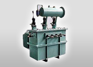
Operating out of our modern production facility at MIDC Rabale, Navi Mumbai, URJA maintains an active export presence across 20+ countries spanning Southeast Asia, the Middle East, Africa, and Latin America. We support global procurement contracts with detailed 3D CAD drawing approvals within 48 hours, customized tropical insulation treatments, and comprehensive FAT inspection witnessing for third-party agencies including Bureau Veritas, SGS, TUV, and Lloyd's Register.
6. Initiate Your High Tension HT Transformer Procurement Today
Whether you are designing a greenfield industrial substation, upgrading an existing distribution network, or procuring custom HT transformers for international EPC projects, URJA Techniques provides end-to-end engineering support, optimized loss calculations, and rapid manufacturing lead times.
Request Technical Specifications & Comprehensive Catalog
Connect directly with our senior application engineers to receive full technical data sheets, dimensional general arrangement (GA) drawings, loss evaluation matrices, and competitive export pricing for your High Tension HT Transformer requirements.
Get Catalog