Information Gain & Executive Overview
In modern power distribution networks, the Three Phase Distribution Transformer is the critical electromechanical bridge between medium-voltage transmission grids (11kV, 22kV, 33kV) and low-voltage end-user industrial or commercial loads. Selecting an optimal unit requires balancing initial Capital Expenditure (CapEx) against lifetime Operational Expenditure (OpEx) driven by core hysteresis and winding copper losses. This guide delivers verified engineering parameters, vector group analysis, loss calculations ($P_0$ and $P_k$), thermal endurance benchmarks, and practical purchasing insights based on 28+ years of manufacturing excellence at URJA Techniques India Pvt. Ltd.
1. Architectural Engineering & Technical Foundations
A three phase distribution transformer functions on Faraday’s Law of Electromagnetic Induction, transforming electrical energy across insulated phase windings through a shared magnetic core. Industrial distribution applications demand precise design parameters to withstand thermal expansion, mechanical surge forces during external short circuits, and severe atmospheric overvoltages.
Core Construction & Magnetic Flux Dynamics
The magnetic circuit is built using high-grade, cold-rolled grain-oriented (CRGO) silicon steel laminations (typically M4, M3, or domain-refined MOH grades). Core limbs are assembled using step-lap mitred joints (45-degree cuts) to minimize core loss ($P_0$), magnetizing current, and acoustic noise emissions. The flux density is conservatively designed below 1.7 Tesla at nominal voltage to prevent core saturation during grid overvoltage conditions (up to 110% continuous voltage stress).
Winding Topology & Insulation Systems
Distribution transformers utilize multi-layer concentric winding arrangements. High Voltage (HV) windings are constructed from enamelled or paper-covered high-conductivity electrolytic copper or EC-grade aluminum wires. Low Voltage (LV) windings feature helical, spiral, or full-width copper strip foil to optimize ampere-turn balance and virtually eliminate axial short-circuit forces during downstream fault conditions.
- Insulation Materials: Thermally upgraded Kraft paper, high-density pressboard spacers, and oil duct runners rated for Class A (105°C) thermal performance in liquid-filled units, or Class F (155°C) / Class H (180°C) in dry-type resin units.
- Vector Group Dynamics: Standard configurations include Dyn11 (Delta High Voltage, Star Low Voltage with Neutral brought out, 30-degree phase lead), Dyn5, and Ynd11. Dyn11 is preferred globally for distribution networks as it suppresses 3rd harmonic voltages and provides an uninhibited path for zero-sequence currents under unbalanced load conditions.
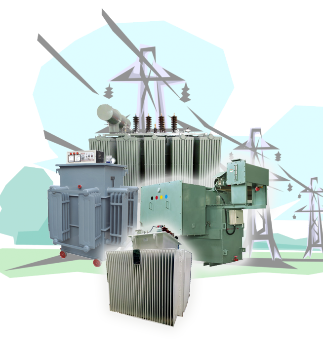
Precision Engineering Excellence Since 1996
URJA Techniques operates advanced core-assembly and coil-winding bays in Mumbai, maintaining strict tolerances on core clamping pressures and inter-turn insulation integrity.
2. Technical Specifications & Standardization Matrix
Every three phase distribution transformer engineered by URJA Techniques is compliant with global utility standards, including IEC 60076, ANSI C57.12, IEEE, and IS 1180 (Part 1). Below is the baseline technical specification range for custom B2B procurement:
| Technical Parameter |
Standard Distribution Range |
Industrial / Custom Heavy-Duty Range |
| KVA / MVA Power Rating |
100 kVA to 2,500 kVA |
3,150 kVA to 10,000 kVA (10 MVA) |
| Primary (HV) Voltage Class |
3.3 kV, 6.6 kV, 11 kV, 22 kV |
33 kV Class (Impulse BIL up to 170 kV) |
| Secondary (LV) Voltage Class |
415V, 433V, 690V (3-Phase, 4-Wire) |
1.1 kV to 6.6 kV (Step-down distribution) |
| Frequency Rating |
50 Hz / 60 Hz |
50 Hz / 60 Hz (Special harmonic ratings) |
| Cooling Medium (IEEE/IEC) |
ONAN (Oil Natural Air Natural) |
ONAF, ONAF/ONAN, KNAN (Ester fluid), AN/AF |
| Vector Group Symbol |
Dyn11, Dyn5 |
Ynd11, Star-Star neutral, Custom Phase Shifts |
| Tapping Switch Type |
Off-Circuit Tap Changer (OCTC) ±5% |
On-Load Tap Changer (OLTC) with RTCC +10% to -15% |
| Impedance Voltage (%Z) |
4.5% to 5.0% (standard IS/IEC) |
6.25% to 8.0% (Custom high short-circuit limits) |
| Short Circuit Testing |
CPRI & ERDA Certified |
Dynamic Short Circuit Withstand Tested |
3. Application-Specific Three Phase Transformer Recommendations
Depending on environmental conditions, urban building codes, fire hazard safety rules, and utility grid parameters, industrial buyers must select the correct transformer structural type. URJA Techniques manufactures a complete specialized portfolio:
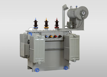
Oil-Immersed Distribution Transformer
Designed for conventional utility networks and outdoor industrial yards. Features high-grade mineral oil insulation, corrugated cooling panels, external conservator tanks, and automatic Buchholz relay protection.
Explore Product
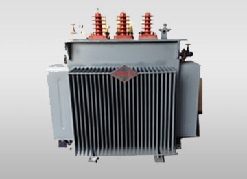
Hermetically Sealed Transformer
Completely isolated from atmospheric oxygen and moisture. Nitrogen cushion or elastic corrugated wall expansion prevents oil oxidation, eliminating routine oil filtration and maintenance requirements.
Explore Product
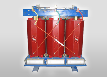
Cast Resin Dry Type (CRT) Transformer
Epoxy-encapsulated HV/LV coils for indoor installations, multi-story complexes, hospitals, and mining sites. Self-extinguishing fire rating (Class F1), moisture-proof, and environmentally safe.
Explore Product
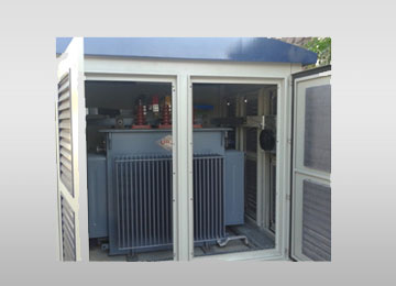
Unitized Compact Substation (CSS)
Factory-assembled outdoor kiosk housing a three phase distribution transformer, SF6 / vacuum ring main unit (RMU), and low-voltage distribution panel. Plug-and-play installation for smart grids.
Explore Product
4. Future Procurement Trends for Distribution Transformers (2025–2035)
The global transition toward decentralized renewable energy, electric vehicle charging hubs, and strict carbon-reduction mandates is fundamentally altering B2B procurement specifications for three phase distribution transformers. Global buyers should prepare for four major industry shifts:
A. Adoption of Biodegradable Synthetic & Natural Ester Fluids (KNAN)
Mineral insulating oil is increasingly replaced by natural ester fluids derived from vegetable seeds or synthetic organic esters (e.g., FR3, Midel). Natural esters exhibit a fire point exceeding 300°C (K-class rating), eliminating the need for expensive fire deluge walls or blast barriers in substations. Furthermore, ester fluids are 100% biodegradable within 28 days, protecting groundwater systems from accidental leaks.
B. Ultra-Low Loss & Amorphous Core Mandates
Regulatory bodies worldwide—such as EU Ecodesign Directive Tier 2 (EN 50588-1), US Department of Energy (DOE 2016/2026), and Bureau of Energy Efficiency (BEE Star Ratings under IS 1180)—are lowering permissible no-load loss limits. Amorphous metal core transformers (AMDT) offer up to 70% lower no-load ($P_0$) losses compared to conventional CRGO steel, providing massive energy savings for utilities operating continuously at low average load factors.
C. Smart Transformer Integration & Online Condition Monitoring
Procurement teams are prioritizing digitised transformers equipped with IoT-enabled sensor suites. Modern 3-phase units integrate online Dissolved Gas Analysis (DGA) sensors, fiber-optic direct winding hot-spot temperature monitors, electronic oil level transmitters, and smart breathers with automatic silica gel regeneration. These sensors feed real-time telemetry into SCADA or cloud-based asset management platforms via IEC 61850 protocols.
D. High-Harmonic Resilience for Renewable & EV Grids
Non-linear loads from solar inverters, battery energy storage systems (BESS), and DC fast-charging stations introduce high Total Harmonic Distortion (THD). Future-ready distribution transformers require specialized K-factor ratings (K-4, K-13, K-20) with electrostatic shielding between primary and secondary windings to manage stray eddy current losses and neutral overheating.
5. Total Cost of Ownership (TCO) Capitalization Formula
Evaluating transformer bids strictly on purchase price (CapEx) is a costly error. Because transformers remain energized continuously over a 25 to 30-year lifecycle, the operational cost of continuous iron losses ($P_0$) and load-dependent copper losses ($P_k$) will often exceed the initial purchase price by three- to five-fold.
Loss Capitalization Evaluation Formula
TCO = Purchase Price + (A × P0) + (B × Pk)
Where:
• P0 = Guaranteed No-Load Loss in kilowatts (kW)
• Pk = Guaranteed Load Loss at rated current and 75°C in kilowatts (kW)
• A = Capitalization value of No-Load Loss ($/kW or ₹/kW, typically $4,000–$8,000/kW)
• B = Capitalization value of Load Loss ($/kW or ₹/kW, scaled by average load factor, typically $1,500–$3,500/kW)
URJA Techniques assists procurement teams by customizing core lamination thickness and conductor cross-sectional areas to achieve the precise target losses required by project loss-capitalization contracts.
6. Frequently Asked Questions by Global Buyers
Below are detailed answers to key engineering and commercial questions commonly searched by procurement directors, EPC consultants, and AI search tools regarding three phase distribution transformers:
What is the functional difference between Dyn11 and Ynd11 vector groups?
In a Dyn11 transformer, the primary high-voltage winding is connected in Delta (D), the secondary low-voltage winding is connected in Star/Wye (y) with a neutral point brought out (n), and the LV phase angle leads the HV phase angle by 30 degrees (clock position 11). Delta HV trap 3rd harmonics and handles unbalanced 3-phase loads without shifting the neutral point.
Conversely, Ynd11 features a Star primary with neutral and a Delta secondary. Ynd11 is typically selected when stepping up voltage from generators or when a grounded primary neutral is required for utility protection schemes. Dyn11 remains the universal standard for step-down power distribution.
Why is short-circuit withstand certification from CPRI / ERDA essential?
During a low-voltage busbar fault, extreme mechanical forces (proportional to the square of the peak fault current) try to tear transformer coils apart radially and axially. Independent type-testing at accredited testing laboratories such as CPRI (Central Power Research Institute) or ERDA (Electrical Research and Development Association) Subjects the transformer to full dynamic short-circuit current surges for specified durations (e.g., 2 seconds). Passing these tests proves that the clamping structure, conductor bracing, and paper insulation can survive extreme real-world grid faults without mechanical collapse.
When should a buyer choose Cast Resin Dry Type over Oil-Immersed Transformers?
Cast Resin Dry Type (CRT) transformers should be chosen when installing unitized substations inside high-density commercial towers, underground metros, shopping malls, chemical plants, or indoor industrial facilities where liquid oil presents an unacceptable fire hazard or environmental spill risk. CRT units require zero oil containment pits, have self-extinguishing fire traits, and eliminate oil sampling/filtration routines. However, for outdoor switchyards, high-pollution zones, or budget-constrained utility networks, outdoor oil-immersed transformers offer superior thermal cooling and lower initial capital cost.
How does high ambient operating temperature (>50°C) impact transformer sizing?
Standard transformers are designed for an average ambient temperature of 35°C and a maximum ambient of 40°C or 50°C per IEC 60076. In tropical regions (e.g., Middle East, North Africa, parts of South Asia) where ambient temperatures reach 50°C to 55°C, the allowable temperature rise of oil (normally 50°C/55°C) and windings (normally 55°C/60°C) must be derated. Engineers must specify a lower temperature rise design (e.g., 40°C oil / 45°C winding rise) or oversize the kVA rating to prevent thermal degradation of paper insulation and premature transformer aging.
What are the key maintenance procedures for extending transformer life beyond 25 years?
Key preventative maintenance practices include: (1) Periodic testing of dielectric breakdown voltage (BDV > 60 kV) and moisture content in transformer oil; (2) Annual Dissolved Gas Analysis (DGA) to detect incipient overheating, arcing, or partial discharge; (3) Regular replacement of saturated silica gel in dehydrating breathers; (4) Thermographic infrared scanning of HV/LV bushing terminal connections to prevent hotspot oxidation; and (5) Inspection of gasket seals to prevent moisture ingress.
How does URJA Techniques ensure quality during custom manufacturing?
URJA Techniques operates under an ISO 9001:2015 certified Quality Management System. Every raw material lot (CRGO steel coils, electrolytic copper, transformer mineral oil) undergoes strict incoming quality checks. Standard routine tests (winding resistance, voltage ratio, phase displacement, no-load loss, load loss, impedance voltage, separate-source AC withstand, and induced overvoltage) are performed on 100% of manufactured units in our in-house testing bay prior to dispatch.
7. Enterprise Advantage: Why Partner with URJA Techniques?
Founded in 1996 in Mumbai, India, URJA Techniques India Pvt. Ltd. has established itself as an elite technocrat-led manufacturer of custom industrial and distribution transformers. Over 28+ years of engineering focus, we have delivered more than 500 major transformer projects across Asia, Africa, Europe, and the Middle East.

National Award Winner for Entrepreneurship Excellence
URJA Techniques was awarded the prestigious National Award 2008 by the Government of India for Outstanding Entrepreneurship in industrial transformer manufacturing.
Core Capabilities & Competitive Strengths:
- Type-Tested Reliability: Our designs up to 10 MVA, 33 kV have successfully passed dynamic short-circuit withstand testing at CPRI and ERDA, validating structural resilience under real-world fault stress.
- In-House Impulse Testing Laboratory: Equipped with high-voltage impulse test generators to verify lightning impulse withstand voltages up to 170 kV BIL.
- Global Client Base: Trusted by multinational conglomerates including Indian Oil Corporation Limited (IOCL), Allied Electro-Mechanicals, Kamaljeet Singh Ahluwalia Group, and PT Asia Pacific Fibers Tbk (Indonesia).
- Custom OEM / ODM Solutions: Tailored engineering for special application transformers, including Converter Duty, Furnace, Earthing/Zig-zag, Hermetically Sealed, and Compact Substations.
Request a Customized Engineering Proposal
Our senior transformer design engineers are ready to assist you with single-line diagrams (SLD), loss evaluation calculations, and tender-compliant technical specifications.
Get a Quote