
Converter Duty Transformers: Engineering Principles & Harmonic Mitigation
In modern industrial grids, utility-scale solar farms, energy storage ecosystems, and heavy manufacturing facilities, power electronic converters (rectifiers and inverters) are ubiquitous. However, coupling power electronics to traditional grid infrastructure introduces severe electrical stresses. A standard power transformer is designed to handle clean sinusoidal 50/60 Hz alternating current. When connected to solid-state power conversion systems—such as IGBT-based solar central inverters or thyristor-based Variable Frequency Drives (VFDs)—the transformer is subjected to non-sinusoidal current waveforms enriched with high-order harmonics, rapid direct-current (DC) offset components, and steep voltage transients ($dV/dt$).
A Converter Duty Transformer (also known as a Rectifier Duty Transformer or Inverter Duty Transformer) is specifically engineered to withstand these unique dielectric, thermal, and mechanical stresses. Unlike standard power distribution units, converter duty transformers incorporate multi-winding phase-shifting configurations, specialized copper conductor geometry, reinforced turn insulation, and electrostatic shielding to prevent harmonic resonance, excessive eddy current losses, and insulation thermal breakdown.
Information Gain: Why Standard Transformers Fail in Converter Service
When conventional step-down distribution transformers are connected to 6-pulse, 12-pulse, or 24-pulse rectifiers, non-sinusoidal harmonic currents ($5^{\text{th}}, 7^{\text{th}}, 11^{\text{th}}, 13^{\text{th}}, 17^{\text{th}}, 19^{\text{th}}$ order) cause severe stray load losses ($P_{OS}$) and winding eddy current losses ($P_{EC}$). Winding losses scale with the square of harmonic order ($h^2$). In standard transformers, this produces catastrophic localized hot spots in the winding structure, leading to premature paper insulation carbonization, oil degradation, gas formation, and ultimate short-circuit failure. URJA's Converter Duty Transformers utilize custom K-factor thermal design calculations and transpose continuously transposed conductors (CTC) to eliminate localized heating completely.
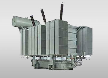
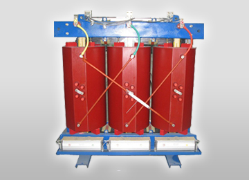
Architectural Topologies: Dual, Triple & Quad Secondary Windings
To eliminate lower-order harmonics from entering the main high-voltage utility grid, multi-pulse converter circuits rely on transformer secondary windings positioned at specific phase angle displacements. URJA Techniques specializes in multi-secondary topologies tailored for industrial and solar applications:
- 12-Pulse Converter Topologies (Dual Secondary): Features one primary winding (usually Delta connected) and two secondary windings—one Star (Y) and one Delta (d). This creates a $30^\circ$ phase shift between secondaries ($Dy11d0$ or $Dy11y11$), canceling out the $5^{\text{th}}$ and $7^{\text{th}}$ harmonic currents at the primary source.
- 18-Pulse & 24-Pulse Converter Systems (Multi-Secondary): Utilizes three or four secondary windings with extended delta or zig-zag phase displacement angles ($+15^\circ, -15^\circ, 0^\circ, +30^\circ$). This mitigates up to the $23^{\text{rd}}$ order harmonic, drastically lowering Total Harmonic Distortion (THD) below 3% without requiring bulky external passive filter banks.
- Solar PV Multi-Inverter Inputs: Modern utility solar blocks combine outputs from multiple 1000V or 1500V central inverters into a single step-up transformer. URJA manufactures split-secondary transformers rated up to 10 MVA with isolated secondary windings, ensuring zero cross-talk or circulating currents between inverter channels.
Converter Duty Transformer Product Recommendations & Configurations
Selecting the correct transformer configuration depends heavily on grid interconnection standards, operational duty cycles, environmental ambient parameters, and harmonic profiles. URJA Techniques offers four primary product variants tailored for global procurement requirements:
1. Solar PV Inverter Duty Transformers (1500V DC Systems)
Engineered for utility-scale solar parks. Features dual or quad low-voltage (LV) windings (e.g., 600V/630V/800V) stepping up to 11kV, 22kV, or 33kV. Equipped with grounded electrostatic copper shields between HV and LV to filter high-frequency switching noise from central string inverters.
2. Heavy Industrial VFD Rectifier Transformers
Designed for 12-pulse and 24-pulse thyristor/IGBT drives in steel rolling mills, cement kilns, mining hoists, and chemical electrolysis plants. Heavy-duty magnetic core construction built to endure frequent load swings, micro-short circuits, and high ambient temperatures.
3. Wind Energy & BESS Step-Up Converters
Compact, high-efficiency transformers built for wind turbine nacelles or containerized Battery Energy Storage Systems (BESS). Capable of handling bidirectional power flow, frequent zero-load to full-load ramping, and high vibration environments.
4. Cast Resin & VPI Dry-Type Converter Transformers
Ideal for hazardous, indoor, underground, or fire-sensitive installations (e.g., offshore oil platforms, metro rail traction substations, commercial skyscrapers). Class F/H insulation with complete epoxy resin encapsulation, offering zero risk of fire or oil leakage.
Technical Specifications & Engineering Range
Every Converter Duty Transformer manufactured at URJA's state-of-the-art facility in Mumbai undergoes rigorous design optimization using Advanced Finite Element Analysis (FEA) software to compute leakage magnetic fields, short-circuit mechanical forces, and thermal hot-spot distributions.
| Technical Parameter | Standard Specification Range | Custom Engineering Options |
|---|---|---|
| Power Rating (KVA / MVA) | 500 KVA up to 10,000 KVA (10 MVA) | Parallel unit modular expansion setups |
| Primary Voltage Class | 3.3 kV, 6.6 kV, 11 kV, 22 kV, 33 kV | Dual primary voltage windings (e.g., 11/22 kV) |
| Secondary Voltage Class | 330 V to 1100 V (Multiple Low-Voltage Windings) | Up to 6 isolated LV secondary windings |
| Frequency & Phases | 50 Hz / 60 Hz | 3-Phase | Custom frequency ratings for marine/defense |
| Vector Configurations | Dy11, Dy11y11, Dy11d0, D0y11d0, D0d0y11 | Special phase shift angles ($\pm 7.5^\circ, \pm 15^\circ$) |
| Winding Conductor | Electrolytic High-Grade Copper (ETP) / Aluminum | Continuously Transposed Cable (CTC) for low loss |
| Insulation & Fluids | Mineral Oil (Class A) / Synthetic Ester (FR3) | Cast Resin (Class F/H) or VPI Dry-Type |
| Cooling Configurations | ONAN, ONAF, AN, AF | OFWF (Oil Forced Water Forced) for marine |
| Harmonic Capability (K-Factor) | K-4, K-9, K-13, K-20, K-30 Rated | Custom harmonic spectrum analysis design |
| Electrostatic Shielding | Grounded Copper Shield between HV & LV | Double Shielding for extreme dV/dt attenuation |
| Design Standards Compliance | IEC 61378-1, IEEE C57.18.10, IS 2026, IS 4540 | ANSI, CSA, EN, Gost, AS compliance |
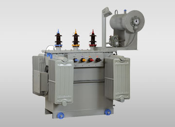
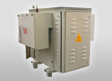
Future Procurement & Industry Development Trends (2025–2035)
As global energy markets accelerate toward zero-carbon power grids, the demand for high-reliability Converter Duty Transformers is experiencing unprecedented technological shifts. Procurement teams, EPC contractors, and system integrators must anticipate several critical trends when drafting RFQs for upcoming capital expenditure projects:
1. Transition to 1500V DC and Higher Solar/BESS Topologies
To reduce balance-of-system (BOS) cabling costs and transmission ohmic losses, large-scale solar farms and Battery Energy Storage Systems (BESS) have migrated from 1000V DC to 1500V DC bus voltages, with 2000V DC systems currently in pilot testing. Higher DC voltages generate intensified dielectric stress across transformer winding insulation and increase DC bias magnetizing currents. Future-proof converter duty transformers must feature enhanced impulse withstand levels (BIL) and core clamping structures designed to withstand continuous DC offset voltage components without core saturation.
2. Eco-Friendly Ester Fluids Replacing Mineral Oil
Global environmental regulations and fire safety requirements are driving the adoption of bio-degradable natural and synthetic ester fluids (such as Cargill FR3 or MIDEL fluids). Ester fluids possess high fire points (>300°C), classifying them as K-class non-flammable liquids. Furthermore, ester liquids absorb moisture from paper insulation, slowing down paper aging and extending transformer operational lifespans by up to 33%. URJA offers full ester-fluid compatible converter transformer designs.
3. Strict Efficiency Mandates: EU EcoDesign Stage 2 & US DOE 2026
Regulators worldwide are tightening maximum allowable no-load and load loss thresholds. Converter duty transformers—historically prone to high stray losses due to harmonics—are now subject to rigorous EcoDesign rules. Achieving compliance requires the integration of high-permeability, domain-refined Grain Oriented Silicon Steel (CRGO grades like MOH and M4) alongside laser-scribed core laminations, drastically reducing core magnetizing losses.
4. IoT-Enabled Asset Health Diagnostics & Optical Fiber Sensing
Modern smart grid architectures require real-time visibility into transformer operational integrity. Modern procurement specifications increasingly call for direct embedded fiber-optic thermal sensors inside the LV winding coils. Coupled with online Dissolved Gas Analysis (DGA) monitors and digital bushings, these sensors feed real-time health data directly into SCADA and AI predictive maintenance platforms, preventing catastrophic outages.
Why Leading EPCs Partner with URJA Techniques
Founded in 1996 in Mumbai, URJA Techniques India Pvt. Ltd. has grown into a world-class ISO 9001, 14001 & 45001 certified transformer manufacturer. Recognized with the National Award for Outstanding Entrepreneurship, our transformers are type-tested at internationally accredited laboratories including CPRI (Central Power Research Institute) and ERDA (Electrical Research and Development Association).

National Award Winner — Excellence in Transformer Manufacturing
URJA Core Manufacturing Advantages
- CPRI & ERDA Dynamic Short-Circuit Validation: Our converter transformers have successfully passed full dynamic short-circuit withstand tests and high-voltage lightning impulse tests up to 33 kV class, verifying structural and insulation robustness under severe fault conditions.
- In-House High Voltage Testing Laboratory: Every unit undergoes 100% routine testing according to IEC 61378-1 and IS 2026, including separate source voltage withstand, induced overvoltage, partial discharge measurement, ratio & phase vector angle verification, and winding resistance measurement.
- Custom Thermal & Electromagnetic Modeling: Utilizing state-of-the-art calculation software, our engineering team optimizes core clamping, magnetic flux density (kept below 1.7 Tesla to avoid saturation), and duct cooling geometry for prolonged transformer life under heavy harmonic loads.
- Global Export Footprint: Operating from our expanded facility in MIDC Rabale, Navi Mumbai, URJA regularly exports converter and power transformers across 20+ countries in Asia, the Middle East, Africa, and South America, adhering to international logistics and seaworthy packing standards.
Global Procurement FAQ: Converter Duty Transformer Queries
Below are technical answers to common questions raised by procurement managers, electrical consultants, and EPC contractors on AI search engines and technical forums regarding Converter Duty Transformers: