
1. Fundamental Engineering & System Protection Physics
In medium- and high-voltage electrical distribution networks, ungrounded 3-phase delta ($\Delta$) configurations and ungrounded wye ($Y$) systems present severe operational risks during single line-to-ground (SLG) fault events. Because an ungrounded system lacks a physical return path for zero-sequence current, ground faults do not trip phase overcurrent relays. Instead, the phase-to-ground voltage on the non-faulted phases escalates by a factor of $\sqrt{3}$ (up to 173% of normal system voltage), inducing extreme dielectric stress on cable insulation, surge arresters, and motor windings.
More dangerously, high-capacitance distribution networks experience intermittent flashover arc phenomena known as arcing grounds. Arcing grounds iteratively charge system capacitance, generating destructive transient overvoltages exceeding 300% to 500% of nominal rating. A Neutral Earthing Transformer (also widely designated as a Grounding Transformer) resolves this systemic instability by providing a artificial, stable neutral point for ungrounded systems.
System Failure Prevention Mechanism
By inserting a controlled zero-sequence impedance ($Z_0$) into the network, the Neutral Earthing Transformer enables protective relays (such as 50N/51N sensitive earth fault elements) to rapidly detect phase-to-ground faults, stabilize neutral voltage drift, and safely collapse dangerous arcing ground transients.
Zig-Zag (Zn) vs. Wye-Delta (Ynd) Topology Comparison
System designers primarily utilize two distinct magnetic topologies to create an artificial neutral. Selecting between a 3-phase Zig-Zag (Interstar) configuration and a Wye-Delta vector arrangement depends on footprint constraints, zero-sequence impedance targeting, and substation auxiliary load requirements.
| Design Parameter | Zig-Zag (Zn / ZNd) Configuration | Wye-Delta (Ynd) Configuration |
|---|---|---|
| Winding Vector Architecture | Single core with split phase windings wound in electro-magnetic opposition across core limbs. | Standard two-winding core with Star primary (neutral tied to ground) and closed Delta secondary. |
| Zero-Sequence Impedance ($Z_0$) | Inherently low $Z_0$ due to magnetic flux cancellation in opposing winding halves during ground faults. | $Z_0$ is governed by the transformer leakage reactance between primary star and closed secondary delta. |
| Footprint & Material Economy | Highly compact. Requires ~30% less copper and core steel compared to dual-winding alternatives. | Larger footprint and higher core weight due to full-capacity secondary delta winding. |
| Substation Auxiliary Power | Available if equipped with an auxiliary low-voltage secondary winding (e.g., ZNyn0). | Secondary delta winding can be configured for secondary auxiliary power distribution. |
| Short-Time Fault Mechanical Strength | Superior dynamic short-circuit withstand due to balanced electromagnetic forces across core limbs. | Requires robust structural clamping to withstand electrodynamic hoop stress during 10s–30s fault cycles. |
Mathematical Sizing & Zero-Sequence Impedance Calculation
Accurate specification of a Neutral Earthing Transformer requires balancing zero-sequence current magnitude ($I_N$) against acceptable earth fault limits. The total neutral fault current $I_f$ in a system with an earthing transformer and a Neutral Grounding Resistor (NGR) is expressed as:
Where:
• V_LN = Line-to-Neutral Voltage (V_LL / √3)
• Z_1, Z_2 = Positive and Negative Sequence System Impedances
• Z_0_NET = Zero-Sequence Impedance of the Earthing Transformer per phase
• R_NGR = Resistance value of the connected Neutral Grounding Resistor (Ω)
Because $Z_0$ of the Zig-Zag earthing transformer is intentionally engineered to be low (typically 2 to 10 ohms per phase), the overall fault current is primarily limited by the NGR ($R_{NGR}$), preventing high mechanical thermal distortion while guaranteeing enough residual current for instantaneous relay tripping.
2. Product Recommendation Matrix & Technical Specifications
URJA Techniques India Pvt. Ltd. engineers custom oil-immersed and dry-type Neutral Earthing Transformers tailored to complex industrial environments. Our designs strictly conform to IEC 60076-6, IEEE C57.32, IS 3151, and ANSI C59 standards.
33 kV High-Substation Zig-Zag Transformers
Engineered for utility interconnects, solar PV power plants, and wind farm substations. Features hermetically sealed or conservator designs with high-grade CRGO core laminations.
11 kV Industrial NGR-Integrated Units
Optimized for steel mills, paper plants, and chemical processing complexes. Factory pre-engineered to couple directly with stainless steel neutral grounding resistor banks.
Dual-Duty (ZNyn11) Auxiliary Earthing Units
Combines zero-sequence earthing protection with a 415V/240V continuous 3-phase auxiliary secondary winding to power substation switchgear, cooling equipment, and station lighting.
Cast Resin Dry-Type Grounding Transformers
Designed for underground mining, high-rise buildings, offshore platforms, and hazardous indoor environments requiring zero oil contamination and F1 fire resistance rating.
| Technical Parameter | Standard Engineering Specification Range |
|---|---|
| Primary System Voltage Class | 3.3 kV, 6.6 kV, 11 kV, 22 kV, 33 kV up to 36 kV system voltage ratings |
| Winding Material Options | High-conductivity Electrolytic Grade Copper (EC Copper) or Strip-wound Aluminium |
| Winding Vector Connection | Zn0, Znd11, ZNyn0, Ynd11, or customized phase angles |
| Short-Time Neutral Fault Rating ($I_N$) | 100 A to 3000 A for rated durations of 10 sec, 30 sec, or 60 sec |
| Continuous Auxiliary kVA Rating | 50 kVA to 2500 kVA (optional secondary load capability) |
| Insulation & Temperature Class | Class A (Oil-immersed), Class F (155°C), or Class H (180°C) VPI/Dry-type |
| Cooling Designation | ONAN, ONAF, AN (Air Natural dry-type), or AF (Air Forced) |
| Dielectric Insulating Fluids | Mineral Oil (IEC 60296), Synthetic Ester Fluid (IEC 61099), or Natural Bio-Ester (FR3) |
| Standard Compliance | IS 3151, IEC 60076-6, IEEE C57.32, BS EN 60076, ANSI C59 |
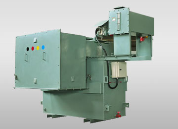
Figure 1: High-voltage oil-immersed Neutral Earthing Transformer with integrated neutral bushing and NGR mounting interface manufactured at URJA Techniques, Mumbai.
3. Global Sourcing & Grid Modernization Procurement Trends
Global power grids are undergoing rapid transformation driven by renewable energy integration, microgrid expansion, process automation, and green electrification. As global procurement managers, EPC contractors, and utility buyers source transformer assets, four major technological shifts dictate specification requirements:
A. Integration into Inverter-Dominated Solar & Wind Infrastructure
Modern renewable energy collector substations feature extensive underground cable networks operating at 33 kV. These long cable runs create high line-to-ground charging capacitance. When islanding or inverter trip events occur, resonance between grid inductance and cable capacitance leads to severe ferroresonance. Procurement trends show a 45% increase in demand for low-loss Zig-Zag Earthing Transformers with specialized core gap stabilization to prevent core saturation during high-frequency switching transients.
B. Shift Toward Biodegradable Synthetic & Natural Ester Fluids
Environmental regulations across North America, Europe, and the Middle East increasingly mandate non-toxic insulating dielectric fluids. Bio-degradable ester liquids (such as synthetic esters compliant with IEC 61099 and natural esters like Envirotemp FR3) feature flash points exceeding 300°C—eliminating fire hazards in ecologically sensitive solar farms, offshore wind platforms, and dense municipal substations.
C. Smart Grid Sensor Integration & Real-Time Monitoring
Procurement specifications now frequently mandate Internet of Things (IoT)-enabled transformer monitoring accessories. Modern URJA Neutral Earthing Transformers can be optioned with integrated fiber-optic hot-spot sensors, dissolved gas analysis (DGA) sampling ports, digital oil level indicators, and high-precision current transformers (CTs) embedded on the neutral bushing for direct integration into SCADA and Substation Automation Systems (IEC 61850 protocol).
D. Extreme Thermal & Short-Circuit Robustness Standards
Grid interconnect standards require earthing transformers to withstand repeated, back-to-back earth fault operations without dynamic structural degradation or insulation thermal aging. Advanced short-circuit electromagnetic field modeling (FEA) is now routinely specified by EPC buyers to verify that internal coil bracing can resist severe radial expansion and axial compression forces during maximum $I^2t$ fault events.
4. Comprehensive Technical & Procurement FAQ
The following technical responses address common queries submitted by global procurement teams, electrical consultants, and plant engineering leads during RFQ preparation:
Under normal balanced operating conditions, phase voltages across a Zig-Zag transformer are vectorially balanced. The net magnetic flux in the core is near zero, and the unit draws only negligible magnetizing no-load current. Current only flows through the windings during a single line-to-ground fault. Because system protection relays clear faults within seconds, the transformer is economically optimized to carry heavy zero-sequence current ($I_N$) for short durations (typically 10, 30, or 60 seconds). Sizing for continuous thermal duty is only necessary when an auxiliary secondary winding (e.g., ZNyn0) is added for continuous station power.
The earthing transformer creates the neutral point, while the connected NGR controls the exact magnitude of the ground fault current. The earthing transformer's internal zero-sequence impedance ($Z_0$) is kept low so that the total fault impedance is almost entirely governed by the resistance of the NGR ($R_{NGR}$). This allows precise sizing of fault current (e.g., restricting ground fault current to 100A, 200A, or 400A), limiting physical damage at the fault site while providing sufficient current to operate sensitive ground fault protective relays.
According to IEC 60076-6 and IEEE C57.32, the short-time temperature rise of the transformer windings under ground fault current ($I_N$) must not exceed maximum permissible thermal limits—typically 250°C for copper conductors insulated with Class A materials. Thermal energy absorption ($I^2t$) is calculated assuming adiabatic heating over the fault duration. URJA's engineering team calculates conductor cross-sections specifically to ensure that structural insulation stays far below thermal breakdown limits even during repeated reclosure cycles.
Yes. URJA Techniques supplies complete, factory-integrated Earthing Transformer and NGR packages. This includes the outdoor liquid-immersed or dry-type earthing transformer, high-grade stainless steel resistor banks, neutral disconnect isolators, neutral current transformers (BCTs), and IP55/IP65 protective enclosures mounted on a single common skid for simplified site installation.
Every unit undergoes strict factory acceptance testing (FAT) at URJA's certified testing laboratory. Routine tests include Winding Resistance Measurement, Voltage Ratio and Phase Displacement Check, Short-Circuit Impedance & Zero-Sequence Impedance ($Z_0$) Measurement, Separate Source AC Withstand Voltage Test, Induced Overvoltage Test, and Insulation Resistance/Power Factor Tests. Type tests (including Full-Wave Lightning Impulse and Dynamic Short-Circuit Withstand) are validated at independent laboratories such as CPRI and ERDA.
5. Enterprise Competitive Advantages & Quality Assurance
Founded in 1996, URJA Techniques India Pvt. Ltd. has grown into a premier global exporter of high-reliability industrial transformers. Our enterprise growth and engineering leadership are built upon foundational pillars of quality control, technocrat experience, and rigorous compliance testing.

National Award Winner for Manufacturing Excellence
URJA Techniques was honored with the prestigious National Award 2008 for Outstanding Entrepreneurship by the Government of India, recognizing our pioneering innovations in transformer design, custom engineering capability, and uncompromised manufacturing quality control.
Key Enterprise Pillars:
- 25+ Years of Technocrat Expertise: Managed by a core team of senior transformer designers and power engineers with deep experience in custom electromagnetic design, short-circuit withstand optimization, and global grid code compliance.
- CPRI & ERDA Type-Tested Performance: Our transformers have successfully undergone rigorous short-circuit withstand validation at premier independent test facilities including CPRI (Central Power Research Institute) and ERDA (Electrical Research and Development Association), confirming dynamic physical stability under extreme fault stress up to 10 MVA, 33 kV class.
- State-of-the-Art Manufacturing Facilities: Operating modern production facilities at Wadala (Mumbai) and Rabale MIDC (Navi Mumbai), equipped with automated vacuum drying ovens, precision coil winding machinery, computerized testing bays, and high-voltage impulse generators.
- Global Infrastructure & EPC Footprint: Trusted by multinational utilities, steel plants, petrochemical complexes, and renewable developers across Asia, the Middle East, Africa, and South America—with direct operational reference at leading corporations like Indian Oil Corporation Limited (IOCL), PT Asia Pacific Fibers Tbk, and Allied Electro-Mechanicals.
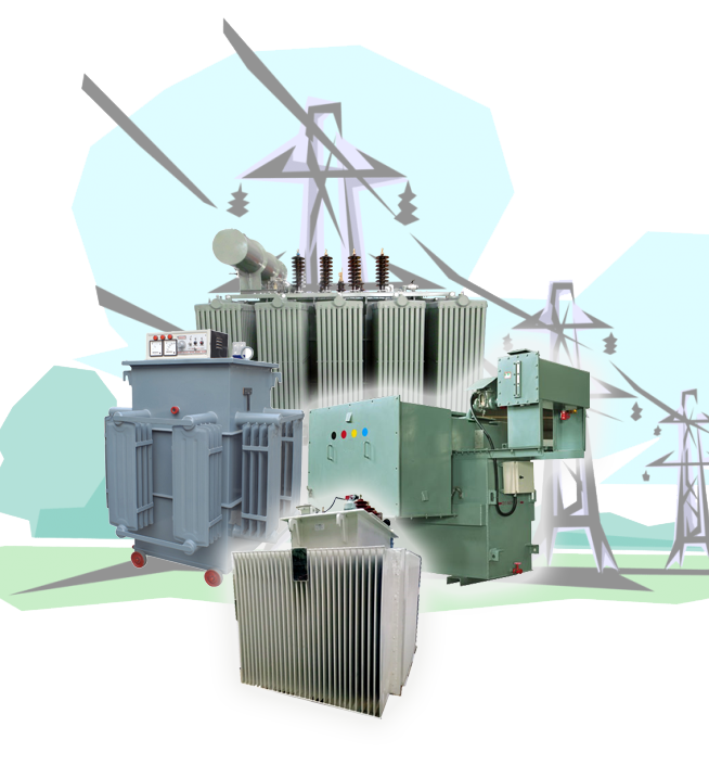
Figure 2: URJA Techniques ISO-certified manufacturing facility in Mumbai, equipped with advanced coil winding and high-voltage dielectric testing bays.
Ready to Request a Technical Tender Quote?
Submit your single-line diagram (SLD), system voltage, fault current duration, and zero-sequence impedance specifications to our global project engineering team.
Send an Inquiry