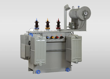
Understanding the Engineering Fundamentals of Multi Winding Transformers
In modern industrial power distribution, renewable grid integration, and heavy-duty variable frequency drive (VFD) applications, electrical engineers frequently encounter complex power quality challenges. Standard two-winding step-down transformers are often incapable of isolating high-frequency harmonics or handling multiple independent loads without incurring massive system footprints and severe thermal dissipation losses. A Multi Winding Transformer (also designated as a multi-secondary transformer or multi-primary phase-shifting transformer) solves these systemic challenges by incorporating three or more electrically isolated windings around a shared high-permeability magnetic core structure.
Unlike conventional step-up or step-down units, a Multi Winding Transformer facilitates multi-circuit energy transformation with precise electromagnetic coupling. By configuring multiple secondary windings with predetermined vector group phase displacements—such as a primary Delta (Δ) feeding dual secondaries configured in Delta (Δ) and Star (Y)—a 30-degree electrical phase shift is created between outputs. When coupled with 12-pulse rectifier bridges, this physical magnetic phase displacement causes the 5th and 7th order harmonic currents to naturally cancel out on the primary side, delivering clean sinusoidal currents back to the utility grid without requiring expensive active harmonic filters.
Technical Insight: Information Gain & Vector Balancing
The primary engineering complexity of a multi-winding transformer lies in maintaining strict impedance matching (within ±5% tolerance) between secondary windings. If cross-coupling leakage impedance is unbalanced, load sharing between rectifier bridges becomes non-uniform, leading to localized copper overheating and premature insulation breakdown. URJA Techniques employs precision electromagnetic field simulations (FEA) to balance radial and axial magnetic forces under symmetrical and asymmetrical short-circuit conditions.
Key Engineering Functions of Multi-Winding Architecture
- Harmonic Mitigation (12-Pulse, 18-Pulse & 24-Pulse Systems): Eliminates low-order current harmonics (5th, 7th, 17th, 19th) directly at the magnetic core interface, compliant with IEEE 519 standards.
- Galvanic Circuit Isolation: Provides complete ground isolation between multiple inverter bridges, preventing circulating ground currents in multi-megawatt solar PV central plants.
- Optimized Physical Footprint: Replaces two or three separate single-secondary transformers with a single integrated unit, cutting substation civil footprint by up to 40%.
- Short-Circuit Dynamic Withstand: Specially interleaved winding geometries absorb asymmetrical mechanical forces during downstream fault conditions.
Featured Multi Winding Transformer Categories
URJA Techniques India Pvt. Ltd. manufactures a wide array of custom-engineered multi-winding units tailored to specific industrial duty cycles. Whether for oil-immersed outdoor substations or indoor flame-retardant dry-type installations, each transformer is constructed under strict ISO 9001 quality controls.
Multi-Secondary Converter Duty Transformer
Designed specifically for multi-pulse thyristor and IGBT rectifiers used in steel rolling mills, arc furnaces, and variable speed motor drives. Features heavy-duty thermal insulation designed for K-factor rating and dynamic harmonic loads.
Explore Specification
Solar PV Central Inverter Transformer
Features dual, triple, or quadruple low-voltage (LV) secondary windings connecting multiple solar central inverters to a single high-voltage (HV) grid interconnection point up to 33 kV. Optimized for maximum solar yield efficiency.
Explore Specification
Cast Resin Dry Type Multi-Winding Transformer
Encapsulated in high-grade epoxy resin under vacuum, offering zero fire hazard, moisture resistance, and minimal maintenance for underground mining, commercial high-rises, offshore platforms, and data centers.
Explore Specification
Technical Specification Matrix: URJA Multi Winding Transformer Range
Below is a standardized technical specification summary for global engineering procurement teams evaluating multi-winding assets:
| Technical Parameter |
Oil-Immersed Multi-Winding Type |
Cast Resin / VPI Dry Type Multi-Winding |
| Power Rating Range |
500 kVA to 10 MVA (Custom Available) |
250 kVA to 5 MVA |
| Primary Voltage Class |
Up to 33 kV (11 kV, 22 kV, 33 kV) |
Up to 33 kV Class |
| Secondary Winding Configurations |
Dual (Dy11y0), Triple (Dy11y0d0), Quadruple Secondary |
Dual Secondary (Dy11y0), Triple Secondary |
| Phase Displacement Angle |
0°, 15°, 20°, 30° (For 12, 18, 24-Pulse Rectification) |
0°, 30° Phase Shift Configuration |
| Impedance Balance Tolerance |
Strictly Controlled within ±3% to ±5% between Secondaries |
Balanced within ±5% across active coils |
| Insulation Thermal Class |
Class A (Oil / Ester Fluid Immersed) |
Class F (155°C) or Class H (180°C) |
| Type-Test Certification |
CPRI & ERDA Certified for Dynamic Short-Circuit & Impulse |
CPRI Tested for Short Circuit & Dielectric Withstand |
| Cooling Designation |
ONAN / ONAF / KNAN (Synthetic Ester Oil option) |
AN / AF (Air Natural / Air Forced with Enclosure) |
| Applicable Design Standards |
IS 2026, IEC 60076, ANSI C57.12, IEEE 519 |
IS 11171, IEC 60076-11, ANSI C57.12.91 |
Enterprise Advantages & E-E-A-T Technical Credentials of URJA Techniques
When procuring mission-critical electrical capital equipment, international EPC contractors, utility companies, and plant engineers prioritize verified manufacturing track records and technical reliability. Established in 1996 in Mumbai, India, URJA Techniques India Pvt. Ltd. has consistently delivered high-performance industrial transformers across global markets for over 28 years.
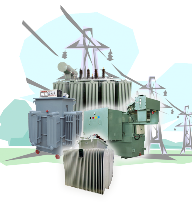
Why World-Class EPCs Trust URJA Techniques
Our modern manufacturing infrastructure located at Rabale, MIDC, Navi Mumbai is equipped with specialized automatic winding machines, vacuum drying ovens, oil purification plants, and an advanced routine testing laboratory capable of full-scale dielectric and impulse testing.
- Independent CPRI & ERDA Type Test Validation: URJA transformers have passed stringent dynamic short-circuit withstand tests at the Central Power Research Institute (CPRI) and Electrical Research and Development Association (ERDA).
- Recognized Industry Excellence: Winner of the prestigious National Award 2008 for Outstanding Entrepreneurship, underscoring our dedication to manufacturing innovation.
- Tier-1 Client Portfolio: Trusted supplier to global enterprises including Indian Oil Corporation Limited (IOCL), Kamaljeet Singh Ahluwalia Steel & Power Division, Allied Electro-Mechanicals, and international installations like PT. Asia Pacific Fibers Tbk (Indonesia).
- Comprehensive Quality Control: ISO 9001 quality management framework overseeing raw material copper purity testing, core lamination burr control, and vacuum impregnation processes.
National Award Winner
Recognized by government authorities for exemplary industrial innovation, precise transformer engineering, and export growth leadership.
100% Quality Inspected
Every unit undergoes strict routine tests including turns ratio, winding resistance, vector group verification, separate source voltage withstand, and partial discharge testing.
Global Export Footprint
Seamless export execution across Asia, the Middle East, Africa, and South America with specialized seaworthy wooden box packaging and export compliance.
Global Procurement & Future Technology Trends in Multi Winding Transformers
As global energy grids undergo massive decentralization and decarbonization, the operational demands placed on multi-winding transformers are evolving rapidly. Technical procurement managers must align their engineering specifications with upcoming technological shifts to prevent early asset obsolescence and ensure maximum lifecycle return on investment (ROI).
1. Hydrogen Electrolyzer Power Supply Units (Green Hydrogen Surge)
Gigawatt-scale green hydrogen production requires ultra-high current DC power supplies. Electrolyzer stacks are driven by massive multi-pulse thyristor or IGBT rectifiers. Multi-winding transformers with up to 4 or 6 phase-shifted secondary windings are rapidly becoming the global standard to feed multi-bridge rectifiers, minimizing grid-side voltage flicker and current harmonics in accordance with strict utility interconnection standards.
2. Transition to Synthetic & Natural Biodegradable Ester Fluids
Environmental regulations and strict fire safety codes in European and North American markets are pushing energy developers to replace traditional mineral oils with synthetic ester fluids (such as MIDEL 7131) or natural vegetable esters. Multi-winding transformers operating with ester fluids feature higher fire points (>300°C), self-extinguishing dielectric properties, and full biodegradability—making them ideal for solar plants near agricultural zones or offshore installations.
3. Integration of Smart Condition Monitoring & Fiber Optics
Because multi-winding transformers experience complex internal thermal distributions across separate secondary coils, conventional top-oil thermometer sensors are insufficient. Modern global procurement guidelines increasingly specify direct Fiber-Optic Temperature Sensors (FOTS) embedded directly inside the innermost secondary winding turns. Combined with IoT-enabled dissolved gas analysis (DGA) sensors, plant operators can monitor thermal hotspots real-time and execute predictive maintenance through AI-driven asset management platforms.
4. Microgrids & Dual-Source Hybrid Distribution
Industrial microgrids combining rooftop solar, battery energy storage systems (BESS), diesel generators, and main utility feeds are utilizing multi-primary and multi-secondary transformers to route bidirectional energy flow dynamically. The multi-winding design provides absolute physical galvanic separation between energy sources, protecting delicate inverter electronics from utility line surges.
Technical FAQ: Multi Winding Transformers (AI & Search Intent Hub)
Below are comprehensive, engineering-validated answers to the most frequent technical queries raised by electrical consultants, procurement officers, and AI search agents worldwide:
Q1: How does a Multi Winding Transformer calculate and balance short-circuit impedance between multiple secondary windings?
Short-circuit impedance balancing in multi-winding transformers is achieved through symmetric physical arrangement of the primary and secondary coils around the magnetic core leg. By using concentric radial placement or split axial stacking, engineers ensure that the leakage magnetic flux path between the primary and each secondary winding remains virtually identical. Impedance is verified using routine 3-phase low-voltage impedance test procedures per IEC 60076-1, ensuring cross-coupling reactance tolerances remain within tight limits (typically ±3% to ±5%).
Q2: What is the primary difference between a 12-pulse and 24-pulse converter duty multi-winding transformer?
A 12-pulse converter transformer features two secondary windings (typically one Delta and one Star) creating a 30-degree phase shift, which cancels out 5th and 7th harmonic currents. A 24-pulse converter transformer incorporates four phase-shifted secondary windings (e.g., +15°, -15°, +45°, -45° relative to primary phase angle or combined extended delta connections). This 15-degree step displacement cancels 5th, 7th, 11th, 13th, 17th, and 19th harmonics, resulting in an exceptionally clean grid current profile with Total Harmonic Distortion (THD) under 3%.
Q3: Why is K-factor rating critical when specifying a multi-winding transformer for industrial motor drives?
Non-linear loads like variable speed motor drives draw nonsinusoidal harmonic currents. Higher-frequency harmonic currents cause increased eddy current losses in copper conductors and stray losses in steel structural parts, generating intense localized heat. A K-factor rating (such as K-4, K-13, or K-20) indicates that the multi-winding transformer has been engineered with double-neutral conductors, specialized conductor transposed strip geometries, and enhanced cooling channels to withstand these additional harmonic stray losses without exceeding thermal insulation limits.
Q4: What maintenance procedures are recommended to maximize the lifespan of an oil-immersed multi-winding transformer?
Key maintenance protocol includes annual insulating oil breakdown voltage (BDV) testing, water moisture content analysis, dissolved gas analysis (DGA) to detect incipient thermal arching or partial discharge, thermographic infrared scanning of high-current secondary bushings, and verification of Buchholz relay and Buchholz pressure relief valves. URJA Techniques provides comprehensive operation & maintenance manuals along with routine testing documentation for every unit dispatched.
Q5: How can global buyers request custom engineering drawings and technical proposals from URJA Techniques?
Buyers can directly contact URJA's engineering sales division with their specific single-line diagrams (SLD), duty cycle specifications, voltage ratings, vector group requirements, and ambient site conditions. Our team provides detailed technical data sheets, dimensional general arrangement (GA) drawings, and commercial quotation proposals within 24 to 48 hours.
Need a Custom Multi Winding Transformer Design for Your Project?
Consult with URJA Techniques' senior transformer design engineers today. We deliver custom-built, CPRI & ERDA tested multi-winding transformer solutions engineered precisely to your technical parameters and global delivery schedule.