1. Executive Overview: Demystifying the Industrial Rectifier Transformer
In modern power-intensive electro-process industries, AC power delivered by grid utility networks must be rectified into high-magnitude direct current (DC). An Industrial Rectifier Transformer (also widely designated as a Converter Duty Transformer) is not merely a standard distribution or power transformer stepping voltage up or down; it serves as the critical electromechanical link feeding semiconductor rectifiers (thyristors, diodes, or IGBTs).
Unlike conventional grid transformers that operate under sinusoidal 50/60 Hz voltages and currents, rectifier transformers are exposed to severe continuous non-sinusoidal current harmonics, extreme mechanical forces during commutation, high thermal stresses, direct current bias saturation, and rapid load cycling. Designing and manufacturing a long-life rectifier transformer demands specialized electromagnetic topology, electrostatic shielding, zero-phase displacement balancing, and structural winding containment.
Information Gain Insight: Why do standard power transformers fail when connected to high-power rectifiers?
Standard transformers are designed for linear loads. When connected to diode or thyristor rectifiers, non-linear harmonic currents (5th, 7th, 11th, 13th, 17th, 19th, etc.) induce excessive eddy current losses in the windings and stray losses in structural clamps and tank walls. This causes localized hot-spotting, rapid thermal degradation of cellulose insulation, and catastrophic dielectric breakdown. URJA Rectifier Transformers incorporate custom K-Factor rating engineering, transposed conductors, and electrostatic shields to neutralize harmonic stress completely.
Core Electrical Topologies: 6-Pulse, 12-Pulse, 24-Pulse & Multi-Phase Rectification
To minimize Total Harmonic Distortion (THD) injected back into the utility high-voltage network and to achieve ultra-smooth DC ripple currents for sensitive electrochemical processes, URJA engineers specialized winding configurations:
6-Pulse Rectification
Utilizes a single secondary winding (Star or Delta). Generates harmonic orders of 6k ± 1 (5th, 7th, 11th, 13th). Suitable for small electroplating, basic DC drives, and auxiliary power supplies where harmonic filtering is installed separately on the AC side.
12-Pulse Rectification
Employs dual secondary windings (one Star and one Delta) phase-shifted by 30 electrical degrees. Effectively cancels out the dominant 5th and 7th harmonics. Reduces input THD significantly while improving rectifier efficiency in heavy chemical plants.
24-Pulse & 48-Pulse Systems
Combines phase-shifting autotransformers or multi-winding primary configurations (e.g., +15°, -15°, +7.5°, -7.5° phase shifts). Virtually eliminates all low-order harmonics (up to 23rd). Crucial for multi-megawatt Green Hydrogen electrolysers and large aluminum smelters.
2. URJA Techniques: Enterprise E-E-A-T & Manufacturing Infrastructure
Founded in 1996 in Mumbai, India, URJA Techniques India Pvt. Ltd. has established an international reputation over 25+ years as a premier transformer design powerhouse. Managed by visionary technocrats, URJA maintains an unyielding commitment to engineering precision, international standard compliance, and extreme operational reliability under heavy duty industrial stress.
Proven Industry Leadership
Type-Tested at CPRI & ERDA for Uncompromising Performance
Every custom Rectifier Transformer engineered at URJA's MIDC Rabale and Wadala manufacturing units undergoes stringent quality controls. Our design methodologies have been validated through rigorous short-circuit withstand type testing at independent accreditation laboratories: the Central Power Research Institute (CPRI) and the Electrical Research and Development Association (ERDA).
In 2008, URJA Techniques was honored with the prestigious National Award for Outstanding Entrepreneurship, testifying to our technical innovation, import substitution capabilities, and global export quality.
Technical Proprietary Features Built into Every URJA Rectifier Transformer:
- High-Grade CRGO Silicon Steel Core: Built using laser-scribed, high-permeability Cold Rolled Grain Oriented (CRGO) steel laminations with step-lap mitered joints to minimize no-load losses, lower magnetizing current, and dampen acoustic noise.
- Harmonic-Resistant Copper Windings: Manufactured with high-purity (99.99%) electrolytic grade oxygen-free copper. Continuously Transposed Conductors (CTC) or thermally upgraded paper-insulated rectangular copper wire are utilized to eliminate localized eddy current loss concentration.
- Electrostatic Shielding: Earth-grounded copper shields located between the High Voltage (HV) primary and Low Voltage (LV) secondary windings block high-frequency transients and common-mode electrical noise from migrating into the semiconductor rectifier bridge.
- Reinforced Mechanical Containment: Massive high-density pressboard insulation blocks, heavy steel clamping rings, and tie-rods provide rigid axial and radial support designed to withstand violent electrodynamic short-circuit forces during DC busbar short circuits.
- Flexible Cooling Modes: Available in ONAN (Oil Natural Air Natural), ONAF (Oil Natural Air Forced), OFAF (Oil Forced Air Forced), and water-cooled OFWF/WF configurations for space-restricted indoor cleanrooms or high-ambient outdoor chemical complexes.
3. Product Selection Matrix & Technical Specifications
Global procurement officers and electrical system design engineers can evaluate URJA’s engineering spectrum for industrial rectifier transformers in the master technical specification table below:
| Parameter / Feature |
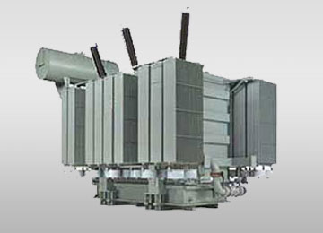
Liquid-Immersed Rectifier Unit |
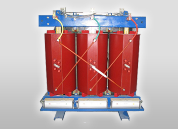
Cast Resin Dry-Type Rectifier Unit |
VPI Dry-Type Rectifier Unit |
| Capacity Rating Range |
Up to 10 MVA (Custom higher on request) |
100 KVA up to 5 MVA |
100 KVA up to 3.5 MVA |
| Primary Voltage Class |
Up to 33 kV (3-Phase, 50/60 Hz) |
Up to 22 kV (3-Phase, 50/60 Hz) |
Up to 11 kV (3-Phase, 50/60 Hz) |
| Secondary Current Output |
Up to 50,000 A DC (via multi-bridge) |
Up to 15,000 A DC |
Up to 10,000 A DC |
| Pulse Configuration |
6-Pulse, 12-Pulse, 24-Pulse, 48-Pulse |
6-Pulse, 12-Pulse, 24-Pulse |
6-Pulse, 12-Pulse |
| Vector Groups & Phase Shift |
Dyn11, Ynd11, Star/Delta dual, +15°/-15° |
Dyn11, YNd11, Star/Star, Star/Delta |
Dyn11, YNd11, Star/Delta |
| Insulation & Dielectric Medium |
Mineral Oil (IEC 60296) / Ester Fluid |
Class F (155°C) or Class H (180°C) Epoxy |
Class H (180°C) Polyester/Silicone Resin |
| Harmonic Mitigation (K-Factor) |
K-13, K-20, K-30 Rated |
K-13, K-20 Rated |
K-4, K-13 Rated |
| Standards Compliance |
IEC 61378-1, IEEE C57.18.10, IS 2026 |
IEC 60076-11, IEC 61378-1, IS 11171 |
IEC 60076-11, IEEE C57.12.01 |
| Typical Industrial Application |
Chlor-Alkali, Green H2, Smelting, Arc Furnace |
Indoor Cleanrooms, Metro Traction, Mining |
Commercial Buildings, Plating Plants |
Recommended Transformer Spectrum for Industrial Rectifier Circuits
URJA Techniques offers a comprehensive suite of custom-tailored transformer equipment manufactured inside our ISO-certified production ecosystem:
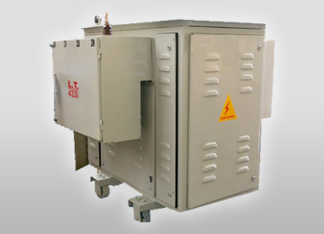
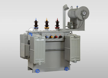
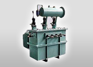
Specially engineered for high-current multi-pulse rectifiers and industrial variable speed drives. Incorporates heavy-duty harmonic suppression and static shielding.
View Specifications
Epoxy resin encapsulated windings offering maximum fire safety, zero risk of fluid leakage, and complete moisture protection for indoor chemical plants.
View Specifications
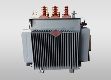
Zero-conservator design preventing oil contact with atmosphere. Eliminates oxidation and moisture absorption, providing maintenance-free operation in coastal areas.
View Specifications
Vacuum Pressure Impregnated coils providing excellent mechanical strength, high dielectric withstand, and resistance to corrosive industrial airborne contaminants.
View Specifications
Designed for severe thermal cycles and mechanical stress in submerged arc, induction, and DC electric furnace applications across steel and metallurgy industries.
View Specifications
Interphase transformers (IPT), DC smoothing reactors, and saturable reactors designed to smooth out current ripples and balance currents in parallel rectifier bridges.
View Specifications
4. Future Procurement Trends & Technological Evolution (2025–2035)
As global energy sectors undergo rapid decarbonization and industrial digitalization, global procurement managers must evaluate several transformative trends when sourcing Industrial Rectifier Transformers:
A. The Green Hydrogen Revolution: Multi-MW Electrolyser Transformers
The transition toward Green Hydrogen production via Polymer Electrolyte Membrane (PEM) and Alkaline electrolysers requires unprecedented Gigawatt-scale DC power conversion infrastructure. Electrolyser rectifiers operate continuously at full rated current, generating severe low-order harmonic spectra. Modern procurement specifications mandate 24-pulse or 48-pulse converter transformers integrated with high-efficiency cooling systems to maximize green hydrogen yield per megawatt-hour of renewable energy input.
B. Biodegradable Ester Fluids (Natural & Synthetic Ester Insulation)
Traditional mineral oil insulation is increasingly being replaced by natural ester (vegetable oil) and synthetic ester fluids (such as Midel 7131 or FR3). Ester fluids offer high fire flash points (>300°C, Class K fire safety rating), complete biodegradability in soil and water, and significantly extend cellulose paper insulation life by absorbing moisture emitted during high-temperature harmonic operation.
C. IoT Digital Twin & Real-Time Condition Monitoring
Smart Rectifier Transformers are now equipped with integrated digital sensor arrays. Real-time parameters monitored via Modbus/IEC 61850 protocol include:
- Fiber-Optic Winding Hot-Spot Temperature Sensors: Direct measurement of internal coil hotspot temperatures caused by harmonic eddy currents.
- Online Dissolved Gas Analysis (DGA): Continuous gas chromatograph analysis detecting trace hydrogen, acetylene, and methane for early insulation failure warning.
- Continuous Partial Discharge (PD) Tracking: Acoustic and UHF sensors detecting internal insulation degradation prior to dielectric fault.
D. Total Cost of Ownership (TCO) & Carbon Footprint Optimization
Enterprise buyers look beyond initial Capital Expenditure (CAPEX) to evaluate Operational Expenditure (OPEX) over a 30-year lifecycle. By choosing URJA's low-loss, high-efficiency Rectifier Transformers, plant owners save tens of thousands of kilowatt-hours annually in reduced structural copper and core hysteresis losses, delivering a typical payback period of less than 24 months.
5. Frequently Asked Questions (FAQ): Industrial Rectifier Sourcing
Below are authoritative technical answers to the most common queries searched by global procurement leads, system integrators, and engineering consultants on Google and AI search platforms:
How do 6-pulse, 12-pulse, and 24-pulse rectifier transformers compare in THD and efficiency?
A 6-pulse rectifier configuration generates primary current harmonics of the 5th, 7th, 11th, and 13th order, resulting in high Total Harmonic Distortion (THD ~ 30-35% on input current). A 12-pulse system uses a 30° phase shift between star and delta secondary windings, canceling out the 5th and 7th harmonics and reducing input THD to approximately 10-12%. A 24-pulse system employs multi-winding phase shifts (e.g., +15° and -15°), eliminating the 5th, 7th, 11th, and 13th harmonics, bringing THD down below 5% without requiring large external harmonic filter banks. Higher pulse counts increase overall system efficiency and protect grid quality.
What causes thermal breakdown in rectifier transformers and how does URJA prevent hotspotting?
Thermal breakdown in converter duty transformers is primarily caused by non-linear harmonic currents. Harmonic currents increase winding skin-effect and proximity-effect losses, creating localized hot spots in the copper conductors and clamping hardware. URJA prevents hotspotting by calculating the specific K-Factor requirement, utilizing Continuously Transposed Conductors (CTC) to equalize current distribution, designing vertical cooling ducts within winding layers, and applying thermally upgraded kraft paper rated up to 120°C continuous operation.
How do green hydrogen electrolysis rectifiers differ from conventional steel plant DC furnace transformers?
Green hydrogen electrolysis rectifier transformers operate at steady-state continuous full DC load 24/7/365 with low secondary voltages (100V to 1000V DC) and extremely high current magnitudes (tens of thousands of Amperes). Conversely, DC Arc Furnace transformers encounter extreme dynamic load swings, frequent short circuits caused by scrap metal bridging electrode arcs, severe voltage flicker, and heavy mechanical vibration. URJA customizes internal impedance, mechanical clamping, and tap-changer range depending on whether the unit is destined for electrochemical electrolysis or steel arc melting.
What routine and type tests are mandatory under IEC 61378-1 and IEEE C57.18.10?
According to IEC 61378-1 (Convertor Transformers) and IEEE C57.18.10 standards, mandatory tests include: Winding Resistance, Voltage Ratio and Vector Group Check, Short-Circuit Impedance and Load Loss Measurement, No-Load Loss and Magnetizing Current Test, Separate-Source AC Dielectric Withstand, Induced Overvoltage Test, and Partial Discharge Measurement. Special type tests include Lightning Impulse Voltage Withstand, Temperature Rise Test under rated harmonic current, and Dynamic Short-Circuit Withstand Validation (as conducted at CPRI & ERDA for URJA transformers).
Why is electrostatic shielding between primary and secondary windings critical?
An electrostatic shield is a grounded copper foil or layer positioned between the high-voltage primary and low-voltage secondary windings. It acts as a capacitive bypass shield, diverting high-frequency voltage transients, switching surges, and common-mode electrical noise directly to ground. This prevents high-voltage spikes from penetrating into sensitive solid-state thyristor or diode semiconductor bridges, preventing rectifier diode blowouts and equipment downtime.
How does URJA ensure short-circuit mechanical strength against DC busbar short circuits?
During a DC busbar short circuit or semiconductor diode breakdown, peak fault currents can reach 15 to 25 times the rated full-load current, inducing massive radial and axial electrodynamic forces. URJA engineers compute short-circuit stresses using finite element magnetic software. We utilize high-density pre-compressed pressboard insulations, rigid heavy-gauge steel clamping rings, hydraulic core clamping structures, and varnish-dip encapsulation to ensure zero winding movement under maximum fault stress.
What is URJA's typical manufacturing lead time, export packaging, and global support policy?
Standard manufacturing lead times range from 8 to 14 weeks depending on rating, custom vector requirements, and third-party inspection schedules. Export shipments are packaged in heavy-duty sea-worthy wooden crates with vapor corrosion inhibitor (VCI) protective wrapping, desiccant bags, and shock/tilt sensors. URJA provides global commissioning supervision, site testing services, spare parts support, and a standard comprehensive warranty backed by over 25 years of global engineering reputation.