
1. Semantic Architecture & Technical Fundamentals of Reactor Transformers
In modern industrial power distribution networks, renewable energy integrations, and heavy manufacturing facilities, power quality degradation presents significant operational risks. As global industrial grids transition toward higher renewable penetration and ultra-fast power electronics (such as Variable Frequency Drives (VFDs), active front-end rectifiers, and arc furnaces), electrical infrastructure encounters severe harmonic pollution, destructive fault surge currents, and reactive power instability. The Reactor Transformer stands as the ultimate inductive defense and power conditioning asset designed to resolve these complex grid anomalies.
Unlike standard power transformers—which are geometrically engineered to minimize internal leakage reactance and maximize secondary voltage coupling—a Reactor Transformer deliberately incorporates continuous, tightly controlled inductive reactance into its magnetic structure. By employing custom-designed gapped iron cores, specialized multi-filar winding techniques, and optimized copper flux density profiles, these units function as dual-action inductive reactors and voltage-matching transformers within a unified, mechanical frame.
Information Gain Key Insight: Core Physics & Air-Gap Stacking
Standard solid iron-core transformers rapidly reach magnetic saturation when subjected to high harmonic currents ($5^{\text{th}}, 7^{\text{th}}, 11^{\text{th}}, 13^{\text{th}}$ order) or severe transient fault surges. URJA Techniques solves core saturation by integrating distributed air gaps precision-segmented by high-grade ceramic or epoxy-bonded spacers along the core limbs. This distributed air gap shifts the magnetic energy storage from the iron laminations directly into the non-magnetic gap space, providing linear inductance ($L$) up to 250% to 300% of nominal current ratings without core clipping or thermal runaway.
Functional Classification of Industrial Reactor Transformers
Global procurement specialists and principal electrical engineers must differentiate between several specialized operational configurations when integrating a Reactor Transformer into single-line diagrams (SLDs):
Series Current-Limiting Reactor Transformers
Connected in series with transmission lines or heavy motor starters to suppress catastrophic short-circuit fault currents ($I_{sc}$). They reduce peak mechanical and dynamic stress on downstream circuit breakers, switchgear assemblies, and busbars.
Detuned Harmonic Filter Reactor Transformers
Engineered with precise de-tuning factors ($p\% = 5.67\%, 7\%, 14\%$) to form resonant series LC circuits with power factor correction capacitor banks. They prevent dangerous parallel resonance amplification and filter high-frequency current harmonics.
Shunt Reactive Compensation Reactors
Connected in parallel to long transmission lines or high-capacitance underground cable networks to absorb excess capacitive reactive power (Ferranti effect), stabilizing steady-state busbar voltage profiles.
Variable Reactor Transformers for Furnace & Drives
Built with combined core elements and split primary windings across independent phase sets. Designed to sustain localized thermal shocks and rapid load changes characteristic of steel arc furnaces and electrochemical refining.
2. High-Performance Product Recommendation & Engineering Spectrum
At URJA Techniques India Pvt. Ltd., every Reactor Transformer is designed by senior power technocrats, manufactured in our state-of-the-art MIDC Rabale, Navi Mumbai facility, and thoroughly tested per IEC 60076-6, IS 5553, and ANSI C57.16 standards. Below is our featured range of recommended reactor solutions for global B2B procurement leaders:
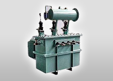
Gapped Iron-Core Reactor Transformer
Engineered with multi-split phase windings and distributed core air-gaps for precise current control, motor soft-starting, and heavy harmonic suppression in high-voltage industrial sub-stations.
View Specifications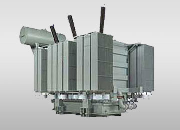
Oil-Cooled Power & Reactor Unit
Dual-function heavy duty units up to 10 MVA, 33 kV featuring inner/outer low-voltage pancake windings and external radiator banks for continuous ONAN/ONAF thermal dissipation.
View Specifications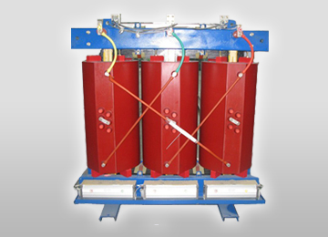
Cast Resin Dry Type Reactor
Vacuum-encapsulated Class F/H epoxy resin windings providing supreme fire safety, zero moisture absorption, and maintenance-free operation in indoor commercial and data center substations.
View SpecificationsMaster Technical Matrix: URJA Reactor Transformer Range
The table below summarizes standard engineering boundaries manufactured by URJA Techniques for global distribution:
| Technical Parameter | Oil-Immersed Gapped Core Reactor | Cast Resin (CRT) Dry Type Reactor | Vacuum Pressure Impregnated (VPI) |
|---|---|---|---|
| Power Rating Range | 100 kVAR up to 10 MVA / 10 MVAR | 50 kVAR up to 5 MVA / 5 MVAR | 25 kVAR up to 3.15 MVA |
| Voltage Class | Up to 33 kV (36 kV max system) | Up to 22 kV Class | 1.1 kV to 11 kV Class |
| Insulation Thermal Class | Class A (Mineral Oil / Synthetic Ester) | Class F ($155^\circ\text{C}$) / Class H ($180^\circ\text{C}$) | Class H ($180^\circ\text{C}$) / Class C |
| Inductance Linearity ($L_n$) | Linear up to 250% $I_n$ | Linear up to 200% $I_n$ | Linear up to 180% $I_n$ |
| Type Test Accreditation | CPRI & ERDA Short-Circuit Verified | CPRI Dynamic Short-Circuit Verified | In-House Impulse & Thermal Tested |
| Enclosure Protection | IP55 / IP65 Hermetically Sealed | IP00, IP23, IP31, IP54 Metal Clad | IP20 to IP44 Ventilated Canopy |
| Cooling Designation | ONAN / ONAF / KNAN (Ester Fluid) | AN (Air Natural) / AF (Forced Air) | AN / AF Forced Ventilation |
3. Future Procurement Trends & Next-Gen Technological Evolution (2025–2030)
As global industries transition toward Net-Zero carbon emissions, high-density AI data centers, microgrid electrification, and renewable hydrogen plants, procurement intent for high-spec Reactor Transformers has fundamentally evolved. Procurement directors are no longer purchasing commodity transformers based solely on initial upfront capital cost (CAPEX); they are utilizing Total Cost of Ownership (TCO) models based on lifecycle losses, thermal endurance, and green fluid compliance.
Synthetic Ester Bio-Degradable Fluids
Traditional mineral oils are rapidly being replaced by synthetic ester dielectric fluids (such as MIDEL 7131). Ester-filled reactor transformers feature fire points $>300^\circ\text{C}$ (K-class fluid rating), eliminating explosion risks in urban or offshore applications while delivering 100% bio-degradability.
Fiber-Optic Distributed Temperature Sensing (DTS)
Modern EPC contractors demand real-time hot-spot monitoring inside reactor windings. URJA integrates optic-fiber sensors directly into core ductways, transmitting continuous temperature telemetry to cloud SCADA systems to prevent insulation thermal breakdown.
Ultra-High Frequency Harmonic Filtering for Solar PV
Large-scale solar PV power plants utilizing central megawatt-scale inverters export high-frequency switching ripple ($2\text{ kHz} - 10\text{ kHz}$). Modern reactor transformers utilize specialized multi-strand Litz wire and thin amorphous core laminations to reduce eddy current skin-effect losses.
Solid-State & Magnetically Controlled Reactors (MCR)
Smart grid substations demand dynamic, stepless reactive power control. Next-generation hybrid reactor transformers allow smooth, thyristor-controlled saturation tuning, providing real-time VAR compensation without mechanical tap-changer wear.
4. Why Global Procurement & EPC Leaders Partner with URJA Techniques
Founded in 1996 by visionary electrical technocrats, URJA Techniques India Pvt. Ltd. has established an unblemished global legacy as a premier manufacturer and exporter of heavy-duty industrial transformers up to 10 MVA, 33 kV. Operating from our modern manufacturing base in Shriram Industrial Estate, Wadala, Mumbai, and full-scale factory setup in MIDC Rabale, Navi Mumbai, URJA delivers customized power engineering excellence tailored to rigorous client specifications.
Key Enterprise Strengths & Quality Benchmarks
Our commitment to absolute engineering integrity, verified performance, and international compliance is substantiated by tangible organizational credentials:
- Independent Type Test Credentials (CPRI & ERDA): URJA's transformer designs have undergone dynamic short-circuit withstand tests at India's premier government-accredited laboratories—Central Power Research Institute (CPRI) and Electrical Research and Development Association (ERDA). Full impulse withstand testing up to 170 kV BIL is performed in-house.
- National Entrepreneurship Award Winner: Winner of the prestigious National Award 2008 for Outstanding Entrepreneurship, affirming our continuous focus on technical innovation, operational transparency, and high-reliability design.
- Zero-Defect Quality Management System: Operating under ISO-certified quality protocols, every unit undergoes exhaustive routine testing including winding resistance, voltage ratio, phase displacement, open-circuit/short-circuit loss measurement, dielectric breakdown voltage, and partial discharge analysis.
- Custom Thermal & Magnetic Simulation: Our engineering team utilizes advanced finite element software to analyze magnetic stray flux leakage, hot-spot thermal gradients, and structural resonance frequencies prior to physical coil winding.
- Robust Export Delivery Infrastructure: Having delivered 500+ major projects across 20+ countries in Asia, the Middle East, Africa, and South America, URJA guarantees seaworthy export packaging, complete documentation, and global technical site support.
Our Rabale factory features automated coil winding machinery, vacuum drying ovens, computer-controlled oil filtration units, and an isolated high-voltage test bay. We handle complete custom fabrications, from precision core stacking to final surface epoxy painting resistant to corrosive saline environments.
5. Global Procurement FAQ: Critical AI-Queried Engineering Solutions
Below are authoritative, technical answers to the most common questions asked by global procurement managers, EPC project directors, and AI search systems regarding Reactor Transformers:
6. Engineering RFQ Specification Checklist for Global Buyers
To expedite engineering design and receive an accurate commercial proposal from URJA Techniques India Pvt. Ltd., global procurement teams are encouraged to provide the key technical parameters outlined in the specification matrix below:
Required Engineering Parameters for Custom Inquiry
- Application Type: Series Current Limiting / Detuned Harmonic Filter / Shunt Reactor / Motor Starting / Furnace Duty
- Rated System Voltage & Frequency: e.g., 3.3kV, 6.6kV, 11kV, 22kV, 33kV @ 50Hz or 60Hz
- Rated Capacity: kVA / MVA or kVAR / MVAR output requirement
- Required Inductance / Impedance: $L$ (mH/phase), Reactance $X_L$ ($\Omega$), or Percentage Impedance $\%Z$
- Harmonic Current Spectrum: Percentage breakdown of $3^{rd}, 5^{th}, 7^{th}, 11^{th}, 13^{th}$ harmonics if applicable
- Short-Time Withstand Current ($I_{kw}$): Rated fault current magnitude (kA) and duration ($t = 1\text{ s}, 3\text{ s}$)
- Enclosure & Cooling Type: Outdoor ONAN (Oil Natural Air Natural), Indoor Cast Resin AN/AF, IP-rating
- Special Conditions: Ambient temperature extremes ($>50^\circ\text{C}$), high altitude ($>1000\text{m}$), seismic zone, saline/marine atmosphere
Ready to Request Technical Specifications or Price Quotation?
Our technical engineering team is ready to analyze your network single-line diagrams, recommend optimized reactor geometries, and deliver competitive export pricing.