
Understanding Electric Furnace Transformers: The Heavy-Duty Powerhouse
In modern steelmaking, ferro-alloy production, and non-ferrous smelting, an Electric Furnace Transformer serves as the critical link between high-voltage grid networks and high-current chemical reduction or thermal melting processes. Unlike standard step-down distribution or power transformers operating under relatively steady state conditions, an electric furnace transformer must continuously withstand short-circuit stresses, extreme thermal fluctuations, rapid load cycling, and severe harmonic distortion.
Global procurement managers and plant engineers searching AI platforms and modern engines for furnace transformer sourcing frequently encounter a knowledge gap regarding the structural mechanics required to withstand dead short-circuits during electrode scrap cave-ins. An electric furnace transformer is fundamentally engineered to convert high supply voltages (such as 11kV, 22kV, or 33kV) into extremely low, stepped secondary voltages (ranging from 80V to over 1000V) capable of delivering thousands to tens of thousands of amperes (up to 100 kA) directly to furnace electrodes or rectifiers.
Key Search Intent Insight for Global Procurement
Why do standard power transformers fail in furnace duty? Standard transformers are designed for nominal currents with predictable surge limits. Electric furnace transformers encounter repetitive electrodynamic forces ($F \propto I^2$) caused by direct arc short circuits during scrap melting. Without reinforced internal busbar bracing, interleaved delta-closures, and specialized On-Load Tap Changers (OLTC), standard units suffer immediate winding deformation and dielectric breakdown.
Electric Furnace Transformer Applications & Custom Configurations
At URJA Techniques India Pvt. Ltd., backed by over 28 years of manufacturing mastery (Est. 1996 in Mumbai), our engineering team designs and manufactures high-performance furnace transformers rated up to 10 MVA and 33 kV class. Each unit is custom-built to comply with rigorous IS, IEC, ANSI, and IEEE C57.17 standards.
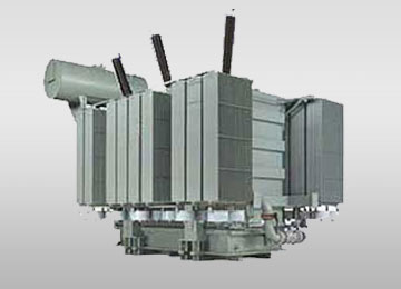
Electric Arc Furnace (EAF) Transformers
Designed for severe mechanical shocks during scrap melting. Equipped with variable secondary voltage steps via OLTC to optimize arc stability and minimize melt times.
Get Catalog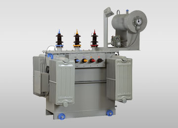
Submerged Arc Furnace (SAF) Transformers
Tailored for ferro-alloy, silicon, and calcium carbide production. High-current continuous duty with water-cooled (OFWF) heat exchangers for 24/7 continuous reduction runs.
Get Catalog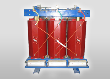
Ladle Refining Furnace (LRF) Transformers
Provides precise temperature holding and metallurgical refining control. Features tight secondary regulation to maintain exact melt chemistry without thermal overshoot.
Get Catalog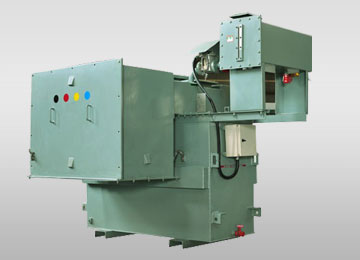
Induction Furnace & Rectifier Transformers
Interfaced with multi-pulse thyristor/IGBT converters (12-pulse / 24-pulse) to isolate high-frequency harmonics while delivering smooth DC or medium-frequency power.
Get CatalogDirect vs. Intermediate Voltage Regulation & Cooling Strategies
When requesting proposals for an Electric Furnace Transformer, buyers must choose between Direct Regulation (tapping on the primary high-voltage winding) and Intermediate Regulation (utilizing a built-in auto-transformer or booster transformer inside the same tank). Below is a proprietary comparison framework designed by URJA Techniques to aid EPC engineers in making informed technical selections.
| Parameter / Feature | Direct Regulation (Primary Tap) | Intermediate / Booster Regulation |
|---|---|---|
| Design Complexity | Simplified single-core active part. Lower footprint. | Dual-core layout (Main core + Booster core) in single tank. |
| Tap Changer Stress | Higher $kV$ insulation stress across tap steps. | Reduced switching stress; constant volts/turn on main core. |
| Capital Expenditure (CAPEX) | Most cost-effective up to 15-20 MVA spectrum. | Higher initial cost; economical for ultra-large EAF units. |
| Secondary Voltage Flexibility | Variable flux regulation or constant flux depending on design. | Wide range of secondary taps at constant secondary current capability. |
| Harmonic Resilience | Requires heavy copper damping shields on secondary. | Booster core absorbs localized transient flux spikes effectively. |
| Cooling Configuration | ONAN / ONAF suitable for smaller ratings; OFWF standard. | Forced liquid circulation (OFAF / OFWF) mandatory for heat dissipation. |
Mechanical Construction Details That Prevent Premature Failure
In actual operation, an Electric Arc Furnace transformer experiences thousands of electrodynamic shock loads daily as arcs ignite, break, and restrike. URJA Techniques addresses these challenges through several engineering innovations:
- Internal Delta-Closure Busbars: By completing the secondary delta connection internally right at the winding terminals rather than outside the tank, stray magnetic flux is drastically reduced. This prevents localized heating of the steel tank cover and improves overall efficiency.
- High-Current Copper Foil & Pancake Windings: Low-voltage secondary windings utilize high-conductivity electrolytic Grade ETP copper sheets or disc windings with multiple parallel transpositions to minimize eddy-current losses.
- Hydraulically Clamped Core Assemblies: Cold-Rolled Grain-Oriented (CRGO) silicon steel laminations (Grade M4 or Hi-B) are clamped using high-strength tie rods and pressure plates to guarantee minimal no-load losses and exceptionally low acoustic noise levels under fluctuating loads.
Global Procurement & Technological Trends in Furnace Transformers
As the global metals industry transitions toward net-zero emissions and decarbonization, the procurement landscape for Electric Furnace Transformers is undergoing rapid evolution. Key macro trends shaping global sourcing decisions include:
1. Decarbonization via Green Steel & Hydrogen-DRI Integration
Traditional blast furnace (BF-BOF) steelmaking is being replaced worldwide by Direct Reduced Iron (DRI) coupled with high-capacity Electric Arc Furnaces (EAF). This shift increases global demand for robust, high-rating furnace transformers capable of running continuous high-power melts on hydrogen-reduced iron pellets, requiring continuous duty ratings with zero unplanned downtime.
2. Transition to Synthetic Ester Dielectric Fluids
Environmental regulations and stringent indoor fire safety protocols are driving steelmakers away from conventional mineral oils. Modern electric furnace transformers are increasingly specified with biodegradable natural or synthetic esters (such as FR3). These ester fluids offer higher fire points (>300°C), thermal insulation enhancement, and complete soil/water protection in the event of accidental leaks.
3. IoT-Enabled Real-Time Health & Dissolved Gas Monitoring
Unscheduled outages in a steel melt shop cost tens of thousands of dollars per hour. Today’s AI-assisted procurement managers demand smart furnace transformers integrated with online DGA (Dissolved Gas Analysis) sensors, fiber-optic direct winding temperature monitoring, and dynamic load-capacity calculators. These systems feed real-time telemetry into plant SCADA networks, enabling predictive maintenance prior to insulation breakdown.
URJA Techniques: Engineering Trust Since 1996
Our credentials reflect a decades-long commitment to engineering perfection, quality assurance, and international compliance.
URJA transformers are independently type-tested for dynamic short-circuit withstand at CPRI (Central Power Research Institute) and ERDA, alongside in-house lightning impulse testing.
Recipient of the prestigious National Award in 2008 for Outstanding Entrepreneurship, recognizing pioneering innovation in specialized industrial transformer designs.
Operating state-of-the-art facilities at Shriram Industrial Estate (Wadala, Mumbai) and Rabale MIDC (Navi Mumbai) under strict quality control regimes aligned to IEC, IS & ANSI.
Trusted supplier across Asia, the Middle East, Africa, and South America, delivering robust transformers engineered for tropical, coastal, and harsh mining environments.

Need Customized Transformer Sizing Support?
Speak directly with URJA's senior design technocrats for technical datasheets and tender specifications.
Get CatalogElectric Furnace Transformer FAQs (Search & AI SGE Query Insights)
Ready to Engineer Your Furnace Power Solution?
Contact URJA Techniques today to discuss technical parameters, request single-line diagrams (SLDs), or receive a comprehensive commercial quotation for Electric Furnace Transformers up to 10 MVA, 33 kV.